EasyManuals Logo

Omega DP41-B User Manual

Omega DP41-B
132 pages
To Next Page IconTo Next Page
To Previous Page IconTo Previous Page
Page #47 background imageLoading...
Page #47 background image
37
7.5.1 COLD JUNCTION COMPENSATION BOARD WIRING
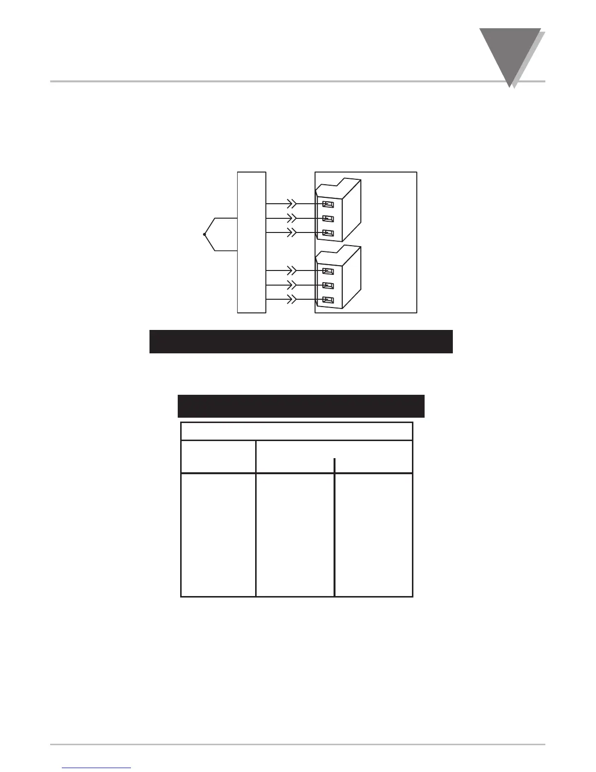
Figure 7-21 shows the wiring hookup for thermocouples. Use the following table to determine which
colored wired get connected to the positive and negative terminals.
Note: Positive (+) and Negative (-) wiring designations are molded into the plastic cover.
Figure 7-21. Directly-Connected Thermocouple
7.5.2 THERMOCOUPLE WIRE COLORS
Table 7-1. Thermocouple Wire Colors
USA
T/C WIRE COLORS
TYPE + LEAD
_
LEAD
J White Red
K Yellow Red
T Blue Red
E Purple Red
N Orange Red
R Black Red
S Black Red
B Gray Red
DIN J Red Blue
METER
+
E
+
S
S
E
+
R
R
P9
P3
1
2
3
1
2
3
+
J1
J2
T/C COLD
JUNCTION
COMPENSATION
BOARD
TC
Signal and Power Input Connections
7

Table of Contents

Other manuals for Omega DP41-B

Questions and Answers:

Question and Answer IconNeed help?

Do you have a question about the Omega DP41-B and is the answer not in the manual?

Omega DP41-B Specifications

General IconGeneral
BrandOmega
ModelDP41-B
CategoryMeasuring Instruments
LanguageEnglish

Related product manuals