7.5 COLD JUNCTION COMPENSATION BOARD INSTALLATION FOR THERMOCOUPLES
To setup the rear protective cover with the P3 and P9 connectors (and Cold-Junction Compensation
Board), proceed with the following (Refer to Figure 7-20).
1)
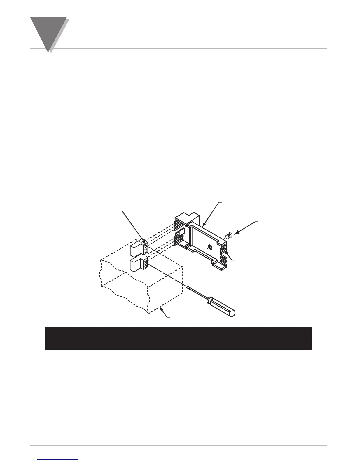
Obtain P3 and P9 connectors and the thermocouple rear protective cover.
2) Put the two (2) connectors P3 and P9 into the corresponding male connectors at the rear of the
meter. Refer to Figure 4-3 for the location of the male connectors. P3 and P9 are identical and
interchangeable connectors.
3) Using a long slotted screwdriver (one that is at least 4” long), loosen the 6 screws on the
connectors.
4) Carefully install the thermocouple rear protective cover onto the connectors making sure the pins
in the rear cover make good contact with the holes in the connectors.
5) Tighten the 6 screws (do not over-tighten).
6) Fasten down the cover with the cover mounting screw.
Figure 7-20. Installation of Thermocouple Cold-Junction Compensation
Board Assembly

 Loading...


