5
Setup
20
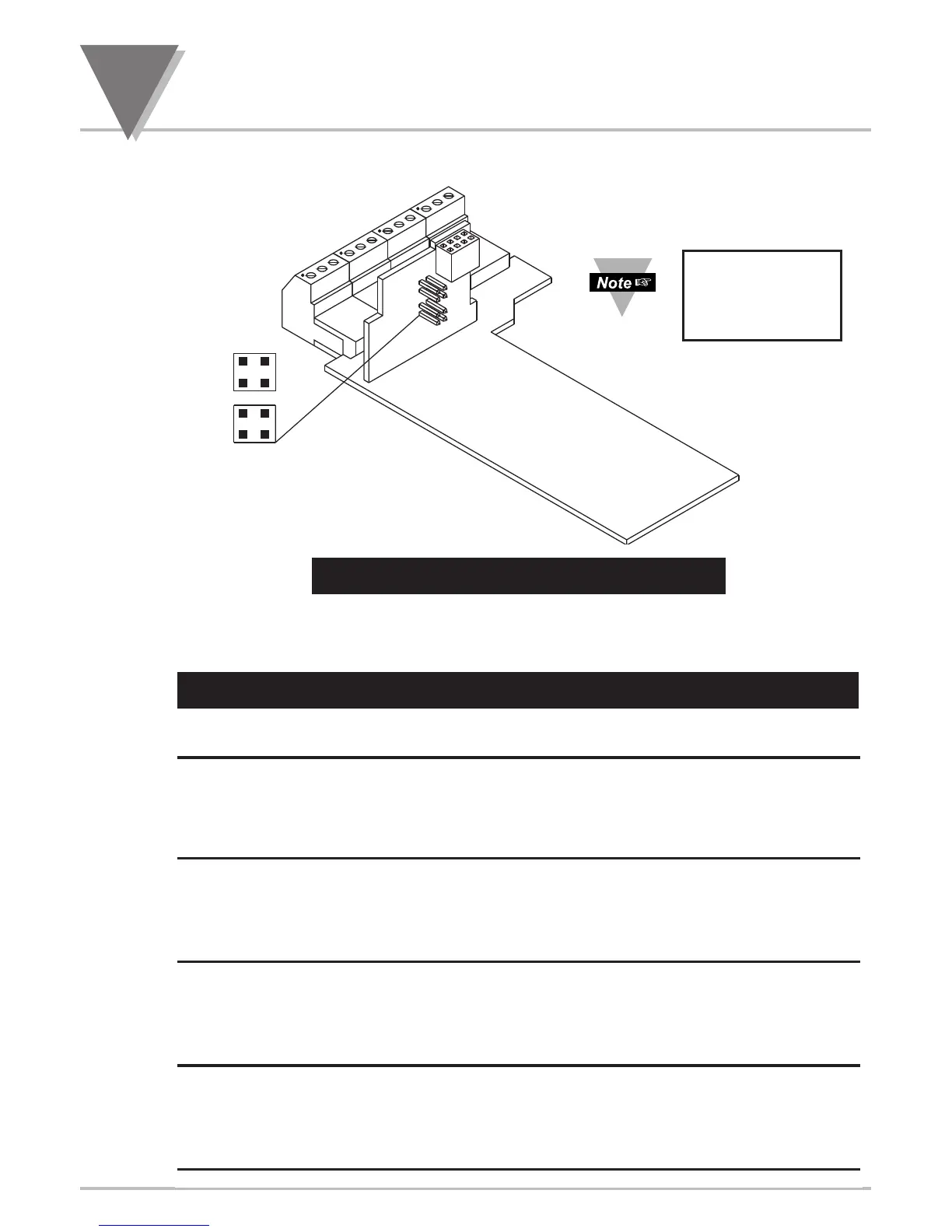
Figure 5-8. 4 Relay Output Option Board
The table below shows which jumpers are assigned to each relay. Defaults have
asterisks.
re 4 Relay Output Board Wiring Connections
Table 5-3 4 Relay Board Jumper Selction
S1 S2 FUNCTION
Assigns SP1 to Relay 1 (P6)
A, C* A, C* Assigns SP2 to Relay 2 (P7)
Assigns SP3 to Relay 3 (P18A)
Assigns SP4 to Relay 4 (P18B)
Assigns SP1 to Relay 3 (P18A)
B, D A, C Assigns SP2 to Relay 2 (P7)
Assigns SP3 to Relay 1 ( P6)
Assigns SP4 to Relay 4 (P18B)
Assigns SP1 to Relay 3 (P18A)
B, D B, D Assigns SP2 to Relay 4 (P18B)
Assigns SP3 to Relay 1 ( P6)
Assigns SP4 to Relay 2 ( P7)
Assigns SP1 to Relay 1 (P6)
A, C B, D Assigns SP2 to Relay 4 (P18B)
Assigns SP3 to Relay 3 (P18A)
Assigns SP4 to Relay 2 (P7)
Refer to your
Relay Output
Option Manual
for more details.

 Loading...


