EasyManuals Logo

Omega DP41-B User Manual

Omega DP41-B
132 pages
To Next Page IconTo Next Page
To Previous Page IconTo Previous Page
Page #41 background imageLoading...
Page #41 background image
31
Signal and Power Input Connections
7
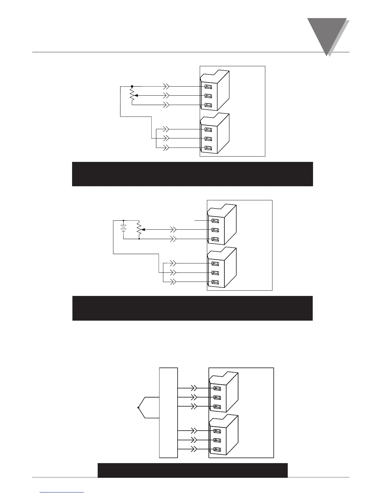
Figure 7-6. Potentiometer Connections with Internal Power
Supply and Ratio Measurement.
Figure 7-7. Potentiometer Connections with External Power
Supply and Ratio Measurement (Remove Jumper S2-G)
7.3 SIGNAL INPUT CONNECTIONS - TEMPERATURE
The following Figures (7-8 through 7-11) show the connections for Thermocouple and RTD Inputs.
Figure 7-8. Directly-Connected Thermocouple
METER
+
E
+
S
S
E
+
R
R
P9
P3
1
2
3
1
2
3
+
J1
J2
T/C COLD
JUNCTION
COMPENSATION
BOARD
TC
METER
NC
+
S
S
E
+
R
P9
P3
1
2
3
1
2
3
-R
JUMPER
USER
PROVIDED
+R
+
E
+
S
S
-E
P9
P3
1
2
3
1
2
3
-R
JUMPER
USER
PROVIDED
METER

Table of Contents

Other manuals for Omega DP41-B

Questions and Answers:

Question and Answer IconNeed help?

Do you have a question about the Omega DP41-B and is the answer not in the manual?

Omega DP41-B Specifications

General IconGeneral
BrandOmega
ModelDP41-B
CategoryMeasuring Instruments
LanguageEnglish

Related product manuals