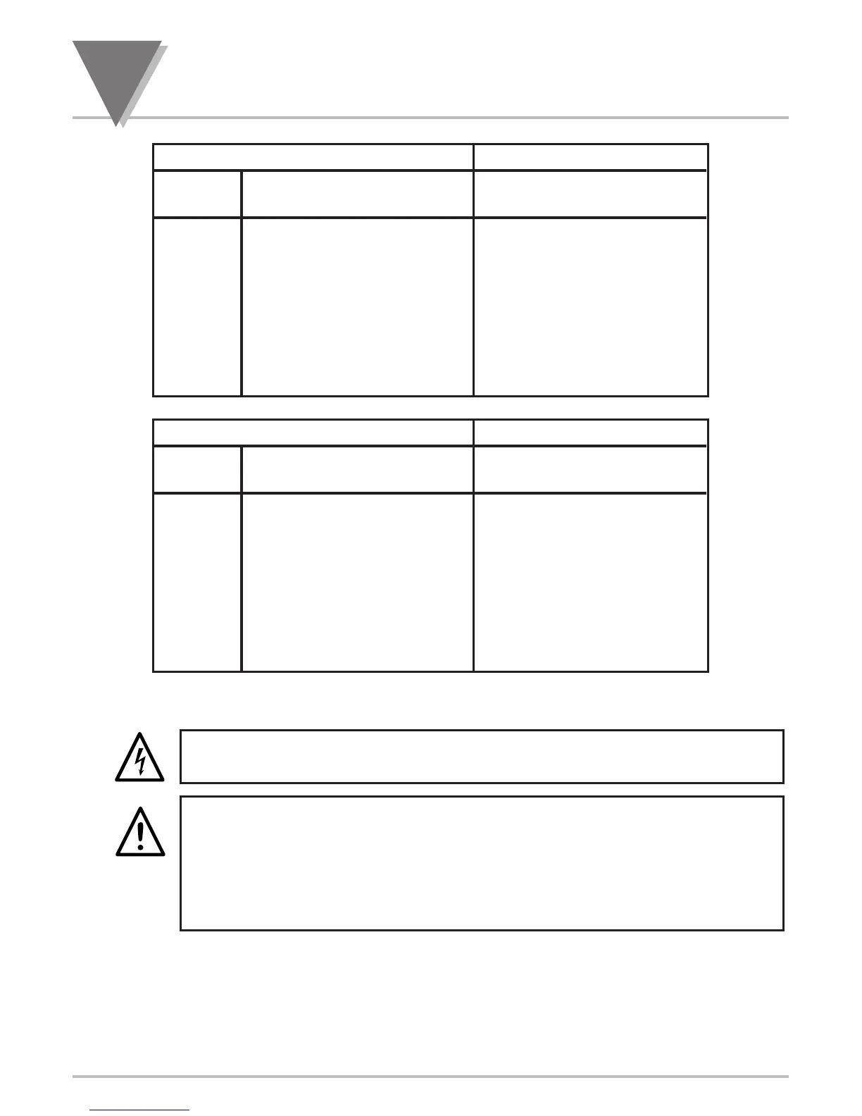
FRANCE GERMANY
T/C WIRE COLORS WIRE COLORS
TYPE + LEAD
_
LEAD + LEAD
_
LEAD
J Yellow Black Red Blue
K Yellow Purple Red Green
T Yellow Blue Red Brown
E Yellow Purple Red Black
N No Standard-See USA No Standard-See USA
R Yellow Green Red White
S Yellow Green Red White
B Use Copper Wire Red Gray
DIN J Red Blue Red Blue
JAPAN UNITED KINGDOM
T/C WIRE COLORS WIRE COLORS
TYPE + LEAD
_
LEAD + LEAD
_
LEAD
J Red White Yellow Blue
K Red White Brown Blue
T Red White White Blue
E Red White Brown Blue
N No Standard-See USA No Standard-See USA
R Red White White Blue
S Red White White Blue
B Red Gray No Standard-See USA
DIN J Red Blue Red Blue
7.6 CONNECTING MAIN AC POWER
Connect the AC main power connections as shown in Figure 7-22.
CAUTION: As mentioned in Section 3.1, the meter has no power ON/OFF switch. The
meter will be ON when power is applied.
WARNING: Do not connect ac power to your meter until you have completed all input
and output connections. Failure to do so may result in injury! This device must only be
installed electrically by specially trained electrician with corresponding qualifications.
The main power input to the unit as well as the AC input signal to be measured must
agree with the wiring instruction. The meter is factory set to the power specified by the
customer at the time of ordering. The voltage is printed on the Product ID Label.
The Safety European Standard EN61010-1 for measurement, control, and laboratory equipment
requires that fuses must be specified based on IEC127. This standard specifies for a Time-lag fuse, the
letter code “T”. The above recommended fuses are of the type IEC127-2-sheet III. Be aware that there
are significant differences between the requirements listed in the UL 248-14/CSA 248.14 and the IEC
127 fuse standards. As a result, no single fuse can carry all approval listings. A 1.0 Amp IEC fuse
is approximately equivalent to a 1.4 Amp UL/CSA fuse. It is advised to consult the manufacturer’s data
sheets for a cross-reference.
7
Signal and Power Input Connections
38

 Loading...


