EasyManuals Logo

Omega DP41-B User Manual

Omega DP41-B
132 pages
To Next Page IconTo Next Page
To Previous Page IconTo Previous Page
Page #28 background imageLoading...
Page #28 background image
Figure 5-5. Main Board
Table 5-1. Main Board Jumper Selections
Figure 5-6. Ethernet Option Board
SW1
J4
SW2
ON
OFF
4
1
P11
DISPLAY
BOARD
SIGNAL
INPUT
BOARD
MAIN
BOARD
POTENTIOMETER
S4
A
J1
J2
J3
J9
S3
S3
R39
S4
POWER
BOARD
C
B
A
SOLDER-SWITCH
"A" & "B"LOCATED
ON UNDERSIDE
OF BOARD
"A"
"B"
TP7
TP6
TP8
AC POWERED UNIT
"A"
"B"
TP7
TP6
TP8
DC POWERED UNIT
5
Setup
18
Refer to your
Ethernet Server
Option Manual
for more details.
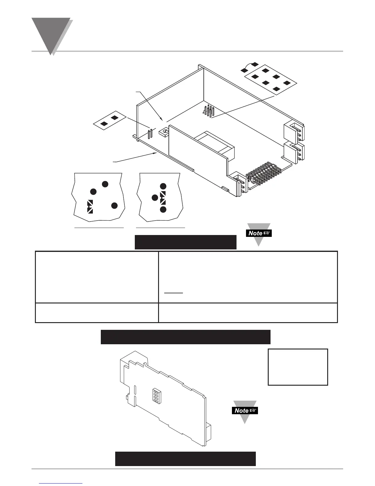
S3A (installed, default) MENU Pushbutton: used for programming
S3A (not installed) MENU Pushbutton: only view settings, but “no store”.
S3B (not installed) Factory Calibration only, DO NOT install.
S3C (installed) Will skip Lockout menus L1.CNF through L4.CNF.
NOTE
: when using MENU1 go to menu LCk.CNF
S3D (installed) Unlocks Front Panel Pushbuttons
S4A (installed) + solder-switch B Selects 10 Vdc Sensor Excitation (default).
S4A (not installed) + solder-switch A Selects 24 Vdc Sensor Excitation.
Default is “OFF” for
all SW2 switches.
SW2 Settings
4 Terminal Server
3 DHCP
2 Mfg Default Settings
1 Serial Port IP Change
D
S3A and S3C used
for MENU2 only.

Table of Contents

Other manuals for Omega DP41-B

Questions and Answers:

Question and Answer IconNeed help?

Do you have a question about the Omega DP41-B and is the answer not in the manual?

Omega DP41-B Specifications

General IconGeneral
BrandOmega
ModelDP41-B
CategoryMeasuring Instruments
LanguageEnglish

Related product manuals