24
78
Alarm Configuration Menu
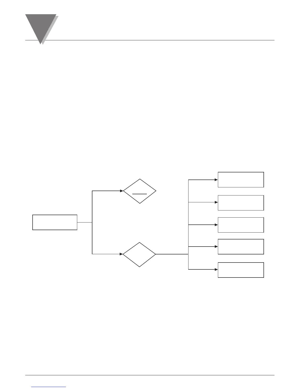
24 ALARM CONFIGURATION MENU: (AL.CNFG)
SP3 and SP4 are often used as Alarm1 and Alarm2, because they have single-sided hysteresis and
can be configured for latching action. The levels of these Setpoints are entered during run mode via the
front-panel pushbuttons (refer to Setpoint Settings Menu Configuration Section 8).
Alarm configuration is used to select or setup:
* The Active Zone for each alarm point (SP3 or AL1, SP4 or AL2) to above or below the setting with
"Act IVE" submenu.
* Independent or ganged operation for SP3 / AL1 or SP4 / AL2 whether or not they should latch
once triggered, "LAtCH" submenu.
*
Whether the normal state of Output Collector or Relay is opened or closed with "N.StAtE"
submenu.
* Following Alarm modes: process (no deviation), high-deviation, low-deviation and band deviation
with "AL.MOdE" submenu.
* The amount of hysteresis or Deadband for the Setpoint3/Alarm1 or Setpoint4/Alarm2 with "AL db"
submenu.
*
Delays in Alarm Action with "NUM.dLy" submenu.
* Enable or disable Alarm points with "RSt AL" submenu.
AL.CNFG ENTER ALARM CONFIGURATION MENU:
Press ‘MENU’ 1) 7 times, Display shows "AL.CNFG" Alarm Configuration Menu.
Press ‘RESET/ENTER’ 2) Display flashes "dISAbL" (default) or previous selection.
Press ‘䊱/MAX’ 3) Select "ENAbLE" to configure Alarm1 (SP3) and Alarm2 (SP4).

 Loading...


