39
Signal and Power Input Connections
7
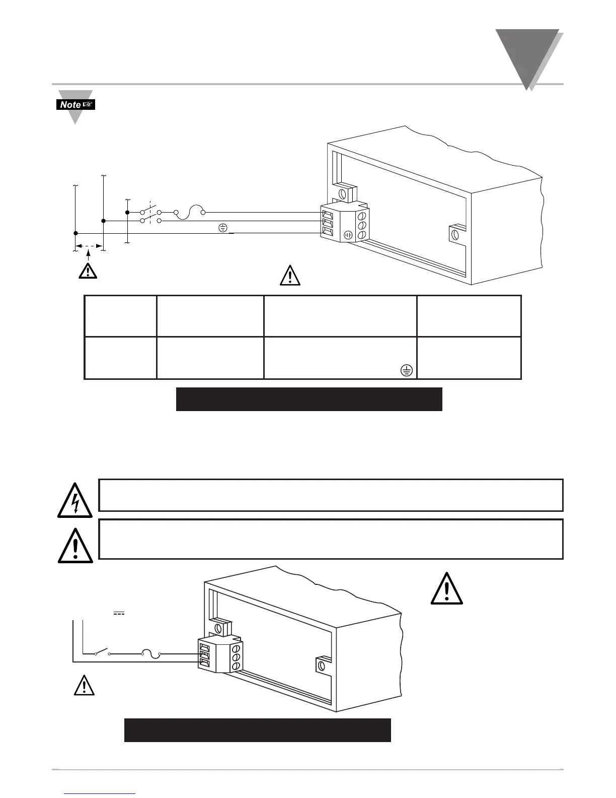
Earth ground MUST be connected to the same earth ground used by the signal source, in
order to achieve published stability and accuracy specifications.
USA EUROPE P1 PIN # ON
WIRING WIRING ORANGE
CODE CODE CONNECTION CON NEC TOR
Black Brown ~ AC Line (L) 1
White Blue ~ AC Neutral (N) 2
Green Green/Yellow ~ AC Protective Ground 3
Figure 7-22. AC Connector Wiring at P1
You are now ready to proceed with setting setpoints as described in Section 8.
7.7 CONNECTING MAIN DC POWER
Connect the DC main power connections as shown in Figure 7-23.
CAUTION: As mentioned in Section 3.1, the meter has no power ON/OFF switch. The
meter will be ON when power is applied.
WARNING: Do not connect dc power to your meter until you have completed all input and
output connections.
Figure 7-23. DC Connector Wiring at P1
You are now ready to proceed with setting setpoints as described in Section 8.

 Loading...


