EasyManuals Logo

Omega DP41-B User Manual

Omega DP41-B
132 pages
To Next Page IconTo Next Page
To Previous Page IconTo Previous Page
Page #43 background imageLoading...
Page #43 background image
33
Signal and Power Input Connections
7
7.4 SIGNAL INPUT CONNECTIONS - STRAIN
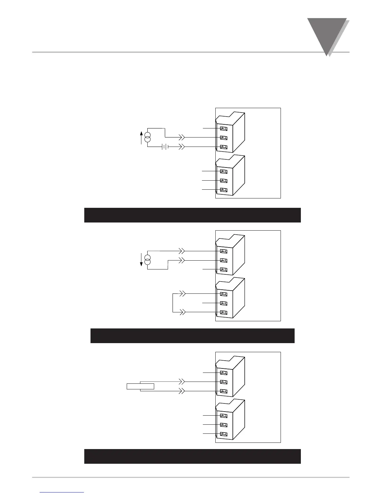
The following Figures (7-12 through 7-19) show the connections for voltage, current and po ten ti om e ter
inputs:
Figure 7-12. Current Input Without Sensor Excitation
rren
Figure 7-13. Current Input With Sensor Excitation
n
Figure 7-14. Voltage Input Without Sensor Excitation
rrent Input With Sensor Excitationge Input Without Sensor Excitation
METER
NC
+
S
S
P9
P3
1
2
3
1
2
3
VOLTAGE
+OUTPUT
-OUTPUT
NC
NC
NC
NC
+
S
S
P9
1
2
3
1
2
3
P3
NC
(+)
(-)
(4-20mA)
+
E
E
JUMPER
USER
PROVIDED
METER
GND
NC
+
S
S
P9
1
2
3
1
2
3
P3
NC
NC
NC
+ -
(4-20mA)
(+)
(
-)
METER

Table of Contents

Other manuals for Omega DP41-B

Questions and Answers:

Question and Answer IconNeed help?

Do you have a question about the Omega DP41-B and is the answer not in the manual?

Omega DP41-B Specifications

General IconGeneral
BrandOmega
ModelDP41-B
CategoryMeasuring Instruments
LanguageEnglish

Related product manuals