Home
Omega
Measuring Instruments
DP41-B
Omega DP41-B User Manual
5
of 1
of 1 rating
132 pages
Give review
Manual
Specs
To Next Page
To Next Page
To Previous Page
To Previous Page
Loading...
8
Setpoint
Settings
Menu
Flowchart
40
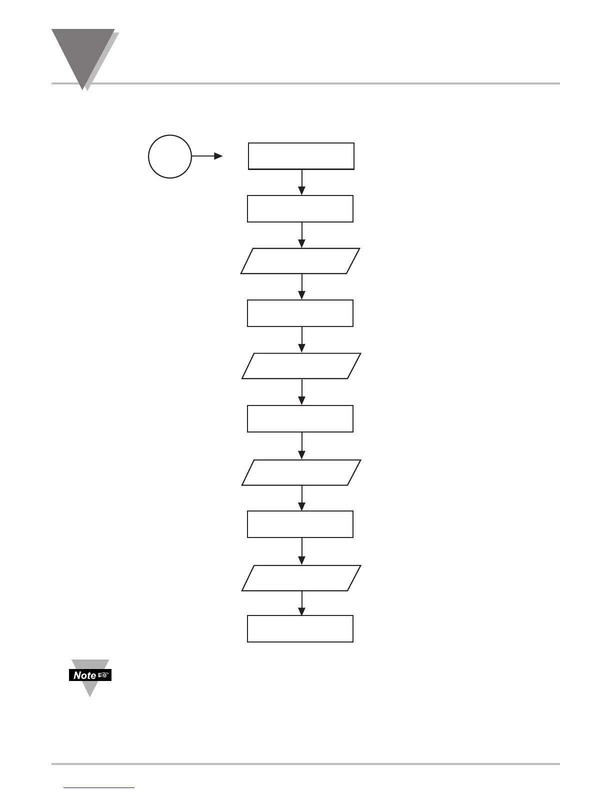
8 SETPOINT SETTINGS MENU FLOWCHART
Once this
‘SETPTS’
button is pressed, each of the four setpoints’
value will be displayed
for approximately 10 sec. in the sequence of this Setpoint Setting Menu Flowchart,
unless the
‘SETPTS’
is repeatedly pushed or setpoint is being edited.
SETPTS
button
SP4
RUN
push
00000.0
00000.0
00000.0
00000.0
:R
u
n mode
:
S
e
t
p
o
i
n
t
1
:
S
e
t
p
o
i
n
t
1
Va
l
u
e
:
S
e
t
p
o
i
n
t
2
:
S
e
t
p
o
i
n
t
2
Va
l
u
e
:
S
e
t
p
o
i
n
t
3
:
S
e
t
p
o
i
n
t
3
Va
l
u
e
:
S
e
t
p
o
i
n
t
4
:
S
e
t
o
i
n
t
4
Va
l
u
e
:R
u
n mode
RUN
SP
1
SP
2
SP
3
49
51
Table of Contents
Default Chapter
3
Table of Contents
3
Introduction
11
Description
11
Features
11
Available Options and Accessories
12
Modes of Operation
13
Unpacking
14
Section 2 Unpacking
14
Safety Considerations
16
Parts of the Meter
17
Front of the Meter
17
Figure 4-1 Front Detail
17
Rear of the Meter
20
Figure 4-2 Connector Label (AC Powered and DC Powered Detail)
20
Figure 4-3 Rear View
21
Table 4-1 Rear Connector Descriptions
21
Setup
22
Conditions Requiring Dissassembly
22
Assembly/Disassembly
22
Figure 5-1 Meter Exploded View
23
Figure 5-2 Board Assembly Removing/Installing Detail
24
Safety Precaution/Product ID Label
25
Figure 5-3 Optional Board Locations
26
Optional Board(S) Installation
26
Figure 5-4 Signal Input Board
27
How to Access Jumpers
27
Figure 5-5 Main Board
28
Figure 5-6 Ethernet Option Board
28
Table 5-1 Main Board Jumper Selection Table
28
Figure 5-7 RS-232/RS-485 Option Board
29
Table 5-2 RS-232 / RS-485 Jumper Selection Table
29
Figure 5-8 4-Relay Output Option Board
30
Table 5-3 4 Relay Board Jumper Selection Table
30
Figure 5-9 Analog Output Option Board
31
Panel-Mount Assembly
31
Figure 5-10 Panel Mounting Assembly
32
Figure 6-1 S1 and S2 Jumper Locations on Signal Input Board
34
Jumper Settings
34
Jumper Positions
35
Thermocouple Input
35
RTD Input
35
For Rtds
35
For RTD 10 Ohm Copper
35
Voltage/Process Value Input
35
For ± 50Mv, 0-100Mv Ranges
35
For ±500 MV, 0-1 V Range
35
For ± 5V, 0-10V Ranges
35
For ± 50V, 0-100V Ranges
36
Current/Process Value Input
36
For 0-20Ma or 4-20Ma Range
36
Bridge Input
36
For ± 50Mv, 0-100Mv Ranges with Internal Excitation
36
For ±50Mv, 0-100Mv Ranges with External Excitation
36
For ± 500Mv, 1V Ranges with Internal Excitation
36
For ± 500Mv, 1V Ranges with External Excitation
36
For ±5 V, 0-10 V Ranges Wtih Internal Excitation
37
For ± 5V, 0-10V Ranges with External Excitation
37
For ± 50V, 0-100V Ranges with Internal Excitation
37
For ± 50V, 0-100V Ranges with External Excitation
37
For 0-20Ma or 4-20Ma Range with Internal Excitation
37
For 0-20Ma or 4-20Ma Range with External Excitation
37
Potentiometer Input
38
Table 6-1 Sensor Excitation Main Board Jumper Selection Table
38
Signal and Power Input Connections
39
Introduction
39
Signal Input Connections -Process
39
Figure 7-1 Current Input Without Sensor Excitation
39
Figure 7-2 Current Input with Sensor Excitation
39
Figure 7-3 Voltage Input Without Sensor Excitation
40
Figure 7-4 3-Wire Voltage Input with Sensor Excitation
40
Figure 7-5 4-Wire Voltage Input with Sensor Excitation
40
Signal Input Connections - Temperature
41
Figure 7-6 Potentiometer Connections with Internal Power Supply and Ratio Measurement
41
Figure 7-7 Potentiometer Connections with External Power Supply and Ratio Measurement
41
Figure 7-8 Directly-Connected Thermocouple
41
Figure 7-9 Potentiometer Connections with 2-Wire RTD
42
Figure 7-10 Potentiometer Connections with 3-Wire RTD
42
Figure 7-11 Potentiometer Connections with 4-Wire RTD
42
Signal Input Connections - Strain
43
Figure 7-12 Current Input Without Sensor Excitation
43
Figure 7-13 Current Input with Sensor Excitation
43
Figure 7-14 Voltage Input Without Sensor Excitation
43
Figure 7-15 3-Wire Voltage Input with Sensor Excitation
44
Figure 7-16 4-Wire Voltage/Bridge Input with Sensor Excitation
44
Figure 7-17 Bridge Input with External Sensor Excitation
44
Figure 7-18 Potentiometer Connections with Internal Power Supply and Ratio Measurement
45
Figure 7-19 Potentiometer Connections with External Power Supply and Ratio Measurement
45
Cold Junction Compensation Board Installation for Thermocouples
46
Figure 7-20 Installation of Thermocouple Cold-Junction Compensation Board Assembly
46
Cold Junction Compensation Board Wiring
47
Figure 7-21 Directly-Connected Thermocouple
47
Table 7-1 Thermocouple Wire Colors
47
Thermocouple Wire Color
47
Connecting Main AC Power
48
Connecting Main DC Power
49
Figure 7-22 AC Connector Wiring at P1
49
Figure 7-23 DC Connector Wiring at P1
49
Setpoint Settings Menu Flowchart
50
Setpoint Settings Menu
51
Section 10 Main Menu Configuration Flowchart
52
SECTION 11 INPUT TYPE MENU FLOWCHART: (Input)
53
Section 12 Input Type Selection
54
Input Type: (THERMOCOUPLE)
54
Input Type: (RTD)
55
Input Type: (DC VOLTAGE/PROCESS VALUE)
56
Input Type: (DC CURRENT)
57
Input Type: (BRIDGE)
58
Input Type: (POTENTIOMETER)
59
SECTION 13 READING CONFIGURATION MENU and FLOWCHART
60
Section 14 Reading Configuration Menu
61
Rd.sc.of Enter Reading Scale and Offset Submenu
61
Unt.tmp Enter Temperature Unit Selection Submenu
65
Dec Pt Enter Decimal Point Configuration Submenu
65
Filter Enter Filter Configuration Submenu
66
Fls.dsp Enter Flashing Display Control Submenu
67
Bright Enter Display Brightness Control Submenu
67
Section 15 Input Configuration Flowchart
68
Section 16 Input Configuration Menu: (Inp.cnf)
69
L IN.FRE Enter Power Frequency Selection Submenu
69
Ad.rate Enter Analog to Digital Rate Submenu
70
Mode Enter Input Mode Configuration Submenu
70
Table 16-1 A/D (Analog to Digital) Rate Option Table
70
Field Calibration for Cold Junction Compensation
71
In.sc.ofenter Input Scale and Offset Configuration Submenu
72
Table 16-2 Factory Calculated Scale Factor Table
74
Section 17 Multi-Point Scale and Offset Menu Configuration Flowchart
75
Section 18 Multi-Point Scale and Offset Menu Configuration: (Mp.sc.of)
76
Table 18-1 Conversion Number Table
78
Table 18-2 Reading/Input Scale & Offset Calculation Table
79
Section 19 Output Configuration Menu Flowchart
80
SECTION 20 OUTPUT CONFIGURATION MENU: (Out.cnf)
81
Ana.out Enter Output Configuration Menu
81
Ot.sc.of Enter Output Scale and Offset Configuration Submenu
83
Section 21 Setpoint Configuration Menu Flowchart
84
Section 22 Setpoint Configuration Menu
85
Section 23 Alarm Configuration Menu Flowchart
87
Section 24 Alarm Configuration Menu: (Al.cnfg)
88
AL 1. CNF Enter Alarm 1 Configuration Menu
89
AL 2.CNF Enter ALARM 2 CONFIGURATION MENU
92
AL Db
93
Num.dly Enter Number of Readings/Display Menu
93
Rst al
93
Enter Alarm Reset Control Menu
93
Section 25 Communication Configuration Flowchart
94
Section 26 Communication Menu Configuration: (Comm)
95
COM.PAR Enter Communication Parameters Submenu
96
Bus.fmt Enter Communication Bus Format Submenu
97
Dat.fmt
101
Modbus Enter Modbus Protocol Submenu
104
Addres Enter Address Selection Submenu
105
Sercnt Enter Serial Count Submenu
105
Section 27 Display Color Selection Menu Flowchart
106
Section 28 Display Color Selection Menu: (Color)
107
N.COLOR Enter Normal Color Submenu
107
SP1.CLR Enter Setpoint 1 Color Submenu
107
SP2.CLR Enter Setpoint 2 Color Submenu
107
AL1.CLR Enter Alarm 1 Color Submenu
107
AL2.CLR Enter Alarm 2 Color Submenu
107
Section 29 Lockout (Access Security) Configuration Menu Flowchart
108
Section 30 Lockout (Access Security) Configuration Menu
109
Section 31 External Control Lines
111
Tare (Pin 1)
111
Peak (Pin 2)
111
Valley (Pin 3)
112
Swlin2 (Pin 4)
112
External Reset (Pin 5)
112
No Connection (Pin 6)
112
Digital Return (Pin 7)
112
Pin 8)
112
Display Hold (Pin 9)
112
LOCKOUT EEPROM (and 'MENU' BUTTON) (PIN 10)
112
RESET of ALARMS (PIN 11)
112
NONSTANDARD RX (PIN 12) and NONSTANDARD TX (PIN 13)
113
No Connection (Pin 14)
113
Ext (Pin 15)
113
Sp1 (Pin 16)
113
Sp2 (Pin 17)
113
Al1 (Pin 18)
113
Al2 (Pin 19)
113
Rtn Ext (Pin 20)
113
Section 32 Troubleshooting
114
Error Mode Messages
114
Flashing "999999" (Numerical Overflow)
114
Flashing "ERR 01" (Offset Overflow)
114
Flashing "ERR 02" (Setpoint Overflow)
114
NOSTOR" & "STORED" (Programming Entries in EEPROM)
114
Flashing "OVLD" (Positive Input Overload)
114
Flashing "OPEN" (Open Sensor Indication)
114
Flashing "-OPEN" (Open Sensor Indication)
115
Flashing "I OVSC" (Input Overscale)
115
Flashing "R OVSC" (Reading Overscale)
115
Flashing "CB OVF" (Count by Overflow)
115
Flashing "UOM.OVF" (Unit of Measure Overflow)
115
Troubleshooting Guide
115
Section 33 Specifications
118
Current Input
118
Voltage Input
118
Potentiometer Input
118
Thermocouple Input
118
RTD Input
119
General
119
Table 33-1 Reading Rate
121
Figure 33-1 Meter Housing and Panel Cutout
122
Flashing Messgaes
123
Thermocouple Table
123
Table 33-2 ITS 90 Thermocouple Tables
123
RTD 10 OHM COPPER Table
124
RTD 385 Table
124
Table 33-3 RTD 10 OHM COPPER
124
Table 33-4 ITS 90 RTD 385
124
RTD 392 Table
125
Table 33-5 ITS 90 RTD 392 US
125
Section 34 Factory Preset Values
127
Section 35 Record Your Setup Values
128
Approval Section
130
Other manuals for Omega DP41-B
Operation Manual
2 pages
5
Based on 1 rating
Ask a question
Give review
Questions and Answers:
Need help?
Do you have a question about the Omega DP41-B and is the answer not in the manual?
Ask a question
Omega DP41-B Specifications
General
Brand
Omega
Model
DP41-B
Category
Measuring Instruments
Language
English
Related product manuals
Omega DP41-W
170 pages
Omega DP41-B Series
94 pages
Omega DP20
30 pages
Omega DP606A
38 pages
Omega DP25-S
68 pages
Omega DP25B-S
68 pages
Omega DP25B-E
74 pages
Omega DPG1000B
4 pages
Omega DPF20 Series
40 pages
Omega Platinum DP32Pt
61 pages
Omega HHF142
30 pages
Omega HHSL402SD
14 pages