101
External Control Lines
31
31 EXTERNAL CONTROL LINES
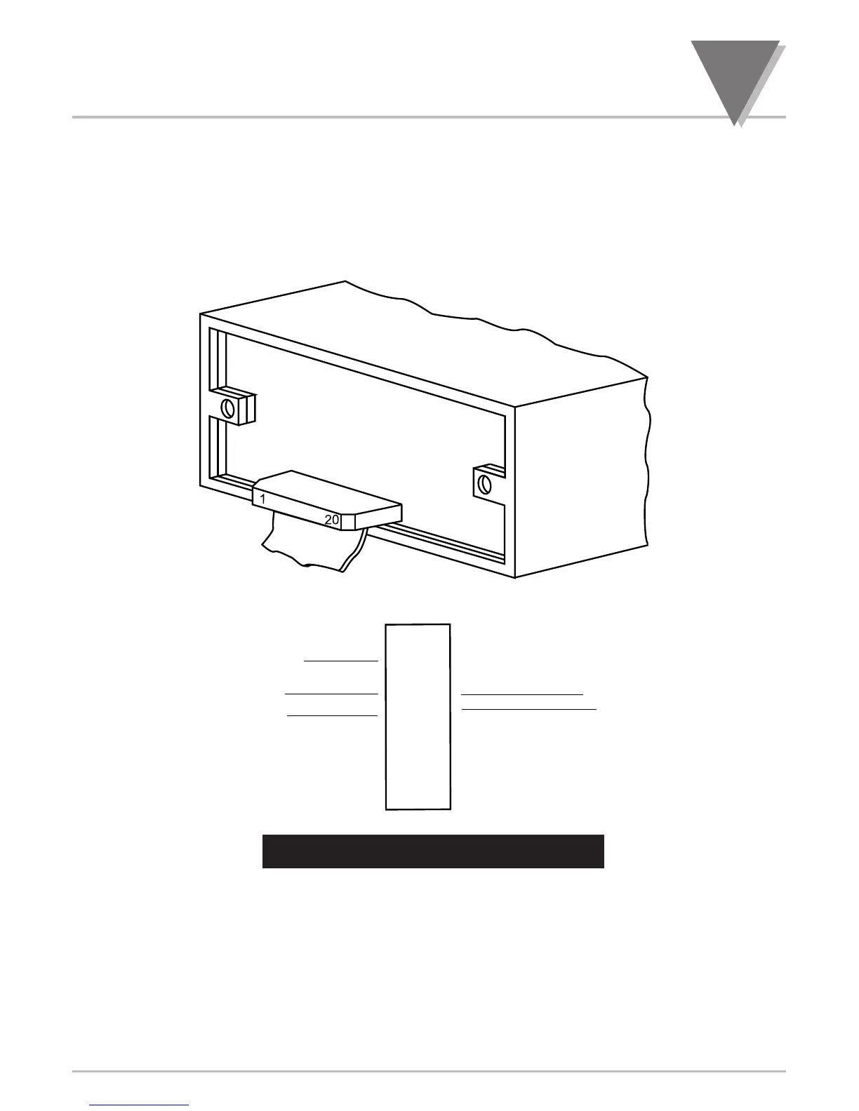
P2, the 20-pin connector at the rear of the main board, connects to the setpoint transistor
collectors and permits remote control of significant meter features.
The meter case label gives the names (abbreviated functions) of each of the twenty pins of P2,
the center-bottom connector. Refer to Figure 30-1.
Figure 30-1. Connector Label Detail
31.1 TARE (PIN 1)
Tare is available when P2-1 and P2-4 are connected to a momentary contact switch. This
feature allows you to automatically zero your meter when the switch is activated. Tare is not
available for temperature meters.
31.2 PEAK (PIN 2)
When this is connected to P2-4 by an external switch, the meter displays the stored PEAK
(“HI RDG”) value rather than the current reading. The display flashes to distinguish this value.

 Loading...


