330
Inverter Positioning Section 5-3
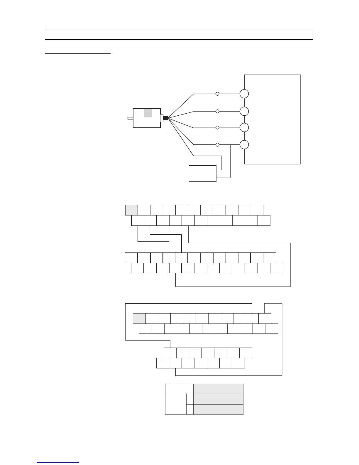
Connection Example
■ Encoder (24 VDC) Connections to High-speed Counter 0
■ Output Terminal Connections to Inverter
■ CP1W/CPM1A-DA041 (Current Output) Connections to Inverter
0 V
+24 V
0.00
0.01
0.04
COM
Differential-phase
Input
Error counter 0: Phase A, 0 V
Error counter 0: Phase B, 0 V
Error counter 0: Phase Z, 0 V
(COM 24 V)
CP1L-@@DT-D
+Vcc
Encoder
(Power supply:
24 VDC)
Black
Phase A
White
Phase B
Orange
Phase Z
Brown
Blue
0 V (COM)
24-V DC power supply
+ 00 01 02 03 04 06 00 01 03 04 06
- COM COM COM COM 05 07 COM 02 COM 05 07
Output word CIO 100
Inverter
PLC
Output word CIO 101
S5 S6 S7 P1 P2 R+ R- FS FR FC
S1 S2 S3 S4 SC PC S+ S- AM AC RP
S5 S6 S7 P1 P2 R+ R- FS FR FC
S1 S2 S3 S4 SC PC S+ S- AM AC RP
1SW2
2
Inverter
IOUT1 VOUT2 COM2 IOUT3 VOUT4 COM4
NC
VOUT1 COM IOUT2 VOUT3 COM3 IOUT4
NC
CPM1A-DA041
Inverter Switch Settings
SW1
NPN
Either setting
ON (Current: I)




 To Next Page