669
Appendix F
Connections to Serial Communications Option Boards
Connection Methods
Communications Modes and Ports
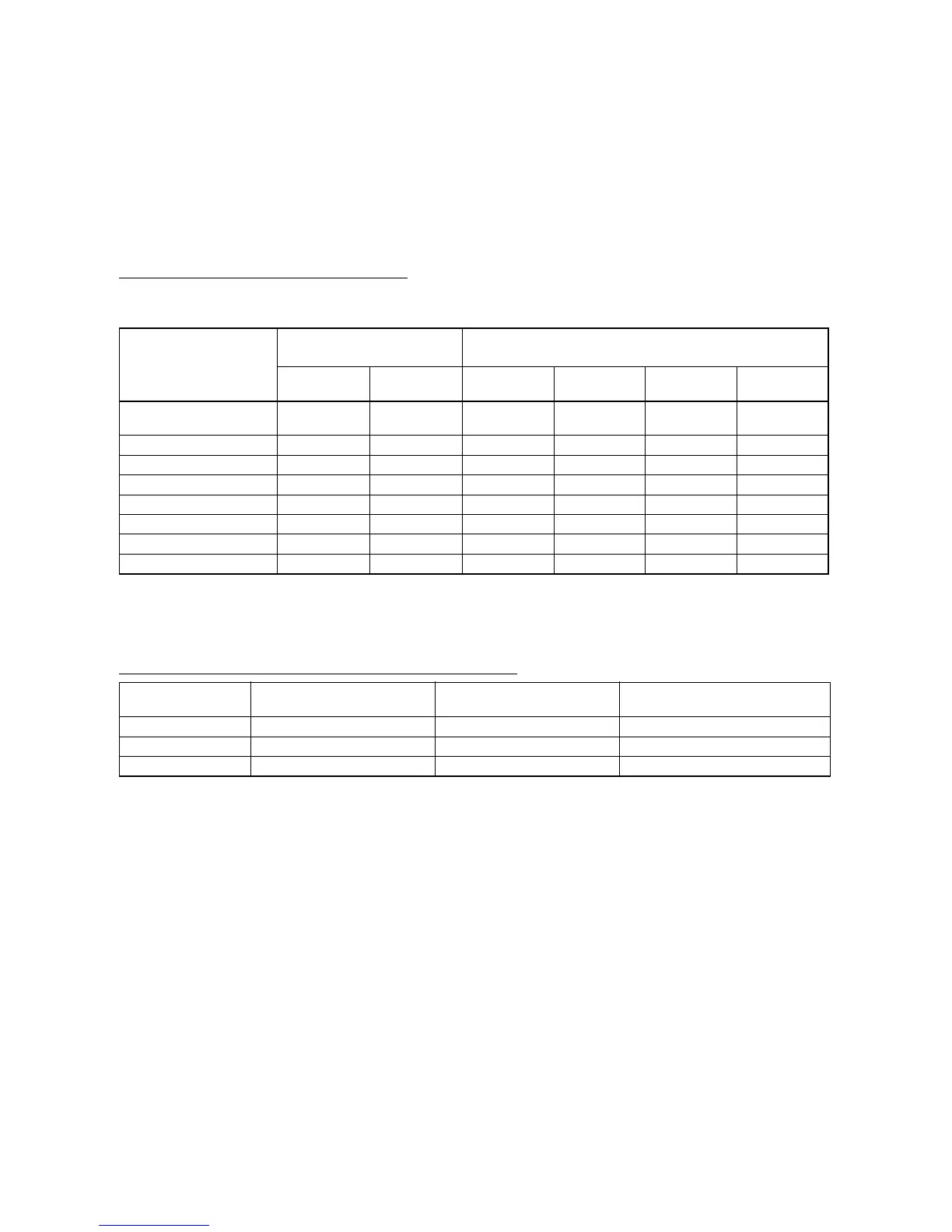
The following table shows the relationship between the communications ports and the communications modes
for the Serial Communications Option Boards.
Note (1) The NT-AL001-E Link Adapter can be used to convert between RS-232C and RS-422A/485 to en-
able 1:N communications.
(2) Use 4-wire connections between Link Adapters.
Models of Serial Communications Option Board
Note The CP1W-CIF11 is a non-isolated board, so the maximum transmission distance is 50 m. For distances
over 50 m, use the RS-232C port on the CP1W-CIF01 and then connect through the NT-AL001-E Link
Adapter, which is isolated. Doing so will enable a maximum transmission distance of 500 m.
Communications mode RS-232C
CP1W-CIF01
RS-422A/485
CP1W-CIF11/CIF12
1:1 1:N
(See note 1.)
1:1 4-wire 1:N 4-wire 1:1 2-wire 1:N 2-wire
Host Link YES YES
(See note 2.)
YES YES No No
Serial PLC Links YES YES YES YES YES YES
Serial Gateway YES YES YES YES YES YES
No-protocol YES YES YES YES YES YES
1:N NT Link YES YES YES YES YES YES
1:1 NT Link YES No YES No YES No
1:1 Link Master YES No YES No YES No
1:1 Link Slave YES No YES No YES No
Model Port Maximum transmission
distance
Connection method
CP1W-CIF01 One RS-232C port 15 m Connector (D-sub, 9-pin female)
CP1W-CIF11 One RS-422A/485 port 50 m (See note.) Terminal block (using ferrules)
CP1W-CIF12 One RS-422A/485 port 500 m Terminal block (using ferrules)