98
Computing the Cycle Time Section 2-7
Here,
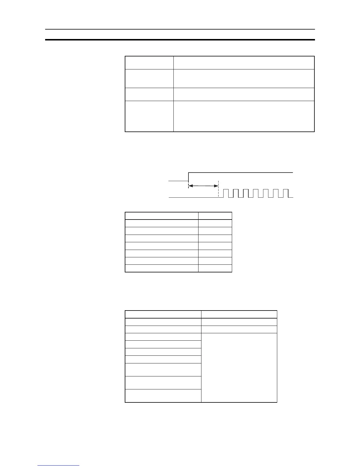
2-7-10 Pulse Output Start Time
The pulse output start time is the time required from executing a pulse output
instruction until pulses are output externally. This time depends on the pulse
output instruction that is used and operation that is performed.
2-7-11 Pulse Output Change Response Time
The pulse output change response time is the time for any change made by
executing an instruction during pulse output to actually affect the pulse output
operation.
Number of partici-
pating slave nodes
The number of slaves to which links have been established
within the maximum unit number set in the master.
Number of non-par-
ticipating slave
nodes
The number of slaves not participating in the links within the
maximum unit number set in the master
Communications
cycle time (ms)
Slave communications time × Number of participating slave
nodes + 10 × Number of non-participating slave nodes
Slave communica-
tions time (ms)
• Communications time set to
Standard
0.4 + 0.286 × ((No. of slaves + 1) × No. of link words × 2 + 12)
• Communications time set to
Fast
0.4 + 0.0955 × ((No. of slaves + 1) × No. of link words × 2 +
12)
Pulse output instruction Start time
SPED: continuous 86 µs
SPED: independent 98 µs
ACC: continuous 103 µs
ACC: independent, trapezoidal 122 µs
ACC: independent, triangular 123 µs
PLS2: trapezoidal 145 µs
PLS2: triangular 146 µs
Start time
Instruction execution
Pulse output
Pulse output instruction Change response time
INI: immediate stop 63 µs + 1 pulse output time
SPED: immediate stop 106 µs + 1 pulse output time
ACC: deceleration stop 1 control cycle (4 ms) minimum,
2 control cycles (8 ms) maximum
PLS2: deceleration stop
SPED: speed change
ACC: speed change
PLS2: target position change in
reverse direction
PLS2: target position change in
same direction at same speed
PLS2: target position change in
same direction at different speed