177
High-speed Counters Section 5-1
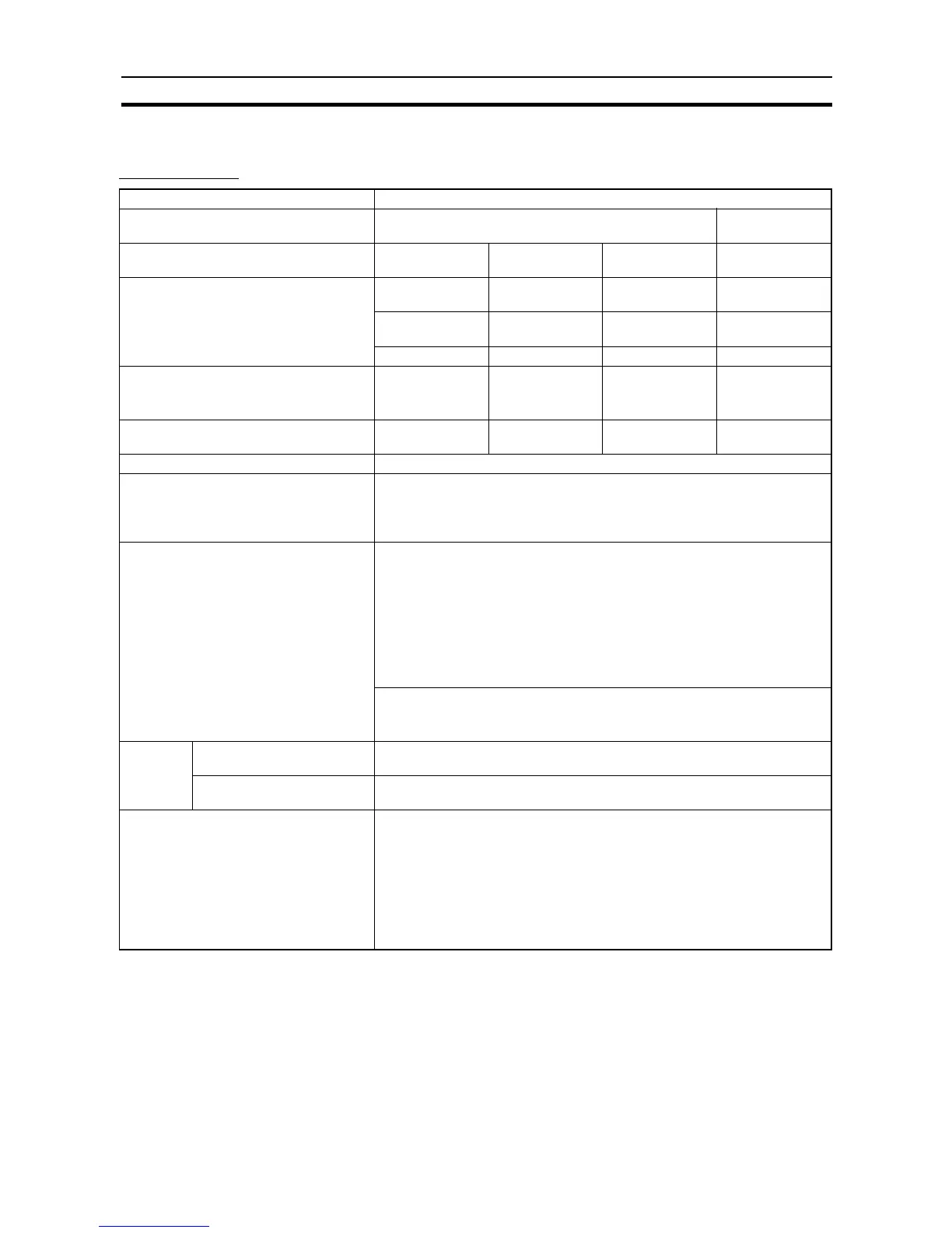
5-1-2 High-speed Counter Specifications
Specifications
Item Specification
Number of high-speed counters 2 (High-speed counters 0 and 1) 4 (High-speed
counters 0 to 3)
Pulse input modes (Selected in the PLC
Setup)
Differential phase
inputs
Up/down inputs Pulse + direction
inputs
Increment inputs
Input terminal allocation Phase-A input Increment pulse
input
Pulse input Increment pulse
input
Phase-B input Decrement pulse
input
Direction input ---
Phase-Z input Reset input Reset input Reset input
Input method Differential phase,
4x
(Fixed)
Two single-phase
inputs
Single-phase
pulse + direction
inputs
Single-phase
input
Response frequency 50 kHz
(J models : 10kHz)
100 kHz
(J models : 20kHz)
100 kHz
(J models : 20kHz)
100 kHz
(J models : 20kHz)
Counting mode Linear mode or circular (ring) mode (Select in the PLC Setup.)
Count values Linear mode: 8000 0000 to 7FFF FFFF hex
Ring mode: 0000 0000 to Ring SV
(The Ring SV (Circular Max. Count) is set in the PLC Setup and the setting
range is 00000001 to FFFFFFFF hex.)
High-speed counter PV storage locations High-speed counter 0: A271 (leftmost 4 digits) and A270 (rightmost 4 digits)
High-speed counter 1: A273 (leftmost 4 digits) and A272 (rightmost 4 digits)
High-speed counter 2: A317 (leftmost 4 digits) and A316 (rightmost 4 digits)
High-speed counter 3: A319 (leftmost 4 digits) and A318 (rightmost 4 digits)
Target value comparison interrupts or range comparison interrupts can be
executed based on these PVs.
Note The PVs are refreshed in the overseeing processes at the start of each
cycle. Use PRV(881) to read the most recent PVs.
Data format: 8 digit hexadecimal
Range in linear mode: 8000 0000 to 7FFF FFFF hex
Range in ring mode: 0000 0000 to Ring SV (Circular Max. Count)
Control
method
Target value comparison Up to 48 target values and corresponding interrupt task numbers can be reg-
istered.
Range comparison Up to 8 ranges can be registered, with a separate upper limit, lower limit, and
interrupt task number for each range.
Counter reset method Select one of the following methods in the PLC Setup.
•Phase-Z + Software reset
The counter is reset when the phase-Z input goes ON while the Reset Bit is
ON.
•Software reset
The counter is reset when the Reset Bit goes ON.
(Set the counter reset method in the PLC Setup.)
Note Operation can be set to stop or continue the comparison operation
when the high-speed counter is reset.