178
High-speed Counters Section 5-1
Auxiliary Area Data
Allocation
Counter Input Modes
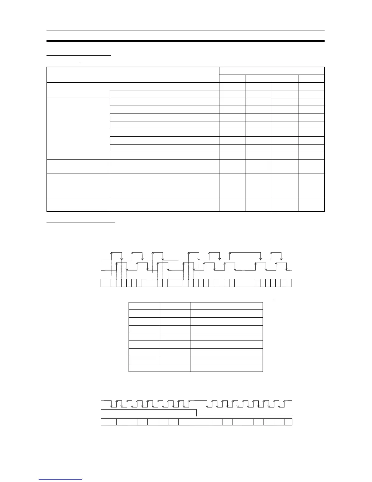
Differential Phase Mode
(4x)
The differential phase mode uses two phase signals (phase A and phase B)
and increments/decrements the count according to the status of these two
signals.
Conditions for Incrementing/Decrementing the Count
Pulse + Direction Mode The pulse + direction mode uses a direction signal input and pulse signal
input. The count is incremented or decremented depending on the status (ON
or OFF) of the direction signal.
Function High-speed counter number
0123
PV storage words Leftmost 4 digits A271 A273 A317 A319
Rightmost 4 digits A270 A272 A316 A318
Range Comparison Con-
dition Met Flags
Range 1 Comparison Condition Met Flag A274.00 A275.00 A320.00 A321.00
Range 2 Comparison Condition Met Flag A274.01 A275.01 A320.01 A321.01
Range 3 Comparison Condition Met Flag A274.02 A275.02 A320.02 A321.02
Range 4 Comparison Condition Met Flag A274.03 A275.03 A320.03 A321.03
Range 5 Comparison Condition Met Flag A274.04 A275.04 A320.04 A321.04
Range 6 Comparison Condition Met Flag A274.05 A275.05 A320.05 A321.05
Range 7 Comparison Condition Met Flag A274.06 A275.06 A320.06 A321.06
Range 8 Comparison Condition Met Flag A274.07 A275.07 A320.07 A321.07
Comparison In-progress
Flags
ON when a comparison operation is being exe-
cuted for the high-speed counter.
A274.08 A275.08 A320.08 A321.08
Overflow/Underflow Flags ON when an overflow or underflow has
occurred in the high-speed counter’s PV.
(Used only when the counting mode is set to
Linear Mode.)
A274.09 A275.09 A320.09 A321.09
Count Direction Flags 0: Decrementing
1: Incrementing
A274.10 A275.10 A320.10 A321.10
1112 11 1010 99 8 88 7 77 666 555 444 333 222 11 0
Phase-A
Phase-B
Count
Phase A Phase B Count value
↑ LIncrement
H ↑ Increment
↓ HIncrement
L ↓ Increment
L ↑ Decrement
↑ HDecrement
H ↓ Decrement
↓ LDecrement
22
1
1
0
0
7 6876
55
44
33
Pulse
Direction
 Loading...


