127
Wiring CPU Unit I/O Section 3-5
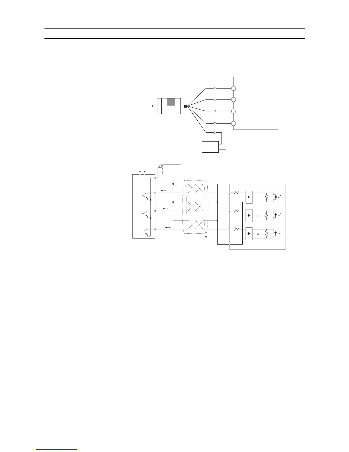
3-5-7 Pulse Input Connection Examples
For a 24-VDC Open-
collector Encoder
This example shows the connections to an encoder with phase-A, phase-B,
and phase Z inputs.
3-5-8 Pulse Output Connection Examples
This example shows a connection to a motor driver. Always check the specifi-
cations of the motor driver before actually connecting it.
For open-collector output, use a maximum of 3 m of wiring between the CP1L
CPU Unit and the motor driver.
No pulses are output while the pulse output transistor is OFF. For a direction
output, OFF indicates that CCW output is in progress.
Do not use the same power supply for both pulse output 24-VDC/5-VDC
power and other I/O power.
Black
White
Orange
+Vcc
Brown
0 V (COM)
Blue
0 V
+24 V
008
009
003
COM
(COM 24 V)
Encoder
(Power supply: 24 VDC)
Example: E6B2-CWZ6C
NPN open-
collector output
Phase A
Phase B
Phase Z
24-V DC power supply
CP1L CPU Unit
(Differential phase input mode)
(High-speed counter 0:
Phase A 0 V)
(High-speed counter 0:
Phase B 0 V)
(High-speed counter 0:
Phase Z 0 V)
Encoder
Power provided.
(Do not use the same I/O power supply as other equipment.)
Phase A
Phase B
Phase Z
Shielded twisted-pair cable
0.00
0.01
0.04
COM
0V
24V
0V
I
A
I
B
I
Z
CP1L CPU Unit
Power
supply