190
High-speed Counters Section 5-1
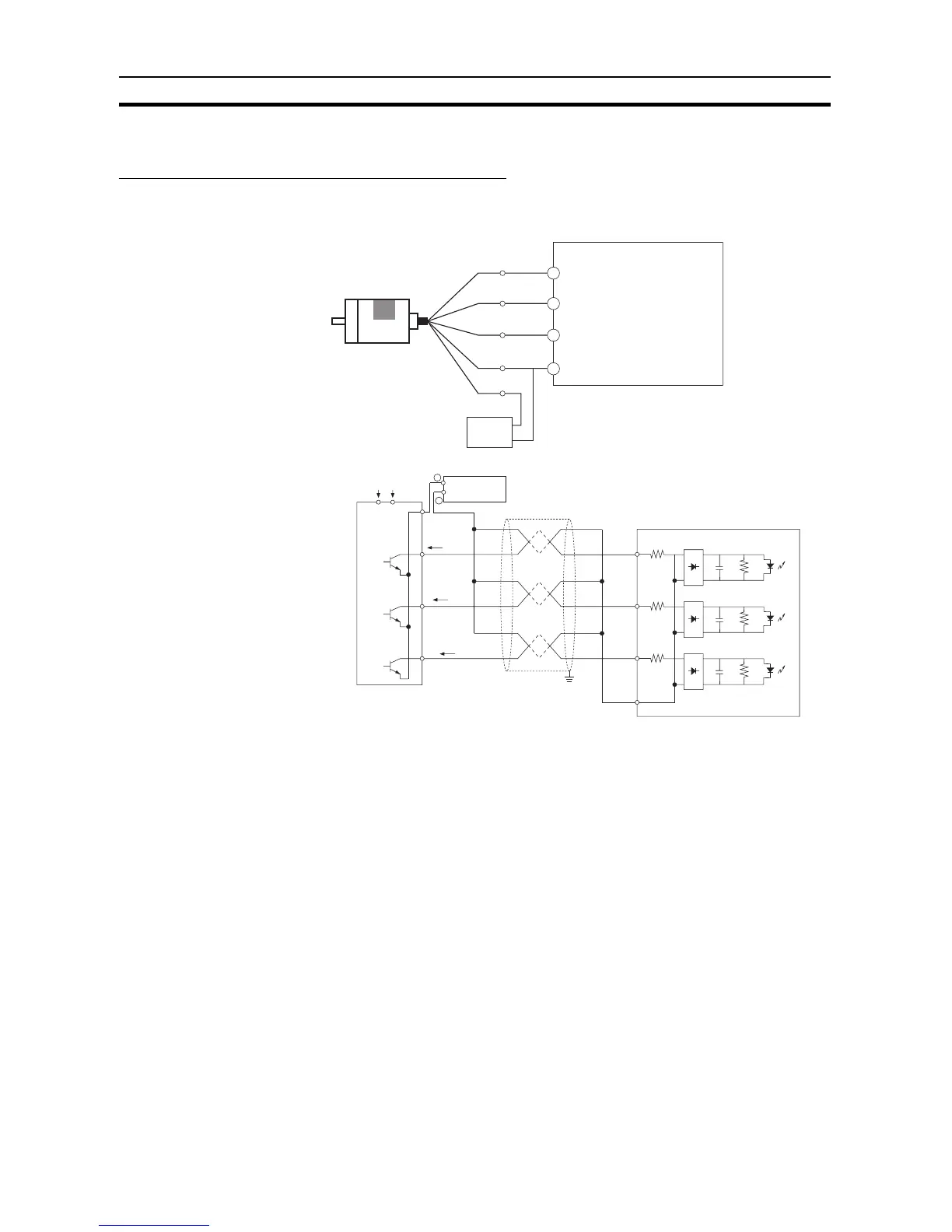
5-1-6 Pulse Input Connection Examples
Encoders with 24 VDC Open-collector Outputs
This example shows how to connect an encoder that has phase-A, phase-B,
and phase-Z outputs.
5-1-7 Ladder Program Example
Inspecting a Dimension by
Counting Pulse Inputs
• This example is for a CPU Unit with 40 I/O Points.
• High-speed counter 0 is used.
• When the edge of the workpiece is detected, the counter PV is reset by a
phase-Z pulse.
• The workpiece is passes inspection if the final count is between 30,000
and 30,300, otherwise the workpiece fails.
• If the workpiece passes, output CIO 100.00 is turned ON by an interrupt
and the indicator PL1 is lit. If the workpiece fails, output CIO 100.01 is
turned ON by an interrupt and indicator PL2 is lit.
• The interrupt program is interrupt task 10.
X/XA CPU Unit
Phase A
Black
Phase B
White
Phase Z
Orange
+Vcc
Brown
0 V
(COM)
Blue
24-VDC power supply
0 V
+24 V
Encoder
(Power: 24 VDC)
Example: E6B2-CWZ6C
(NPN open-collector
output)
0.00
(High-speed counter 0: Phase A, 0 V)
(Differential Input Mode)
0.01
(High-speed counter 0: Phase B, 0 V)
0.04
COM
(High-speed counter 0: Phase Z, 0 V)
(COM 24 V)
0.00
0.01
0.04
COM
0 V
24 V
Power
0 V
Encoder
Power supply
−
Shielded twisted-pair cable
(Do not use the same power supply as for other I/O.)
IA
IB
IZ
Phase A
Phase B
Phase Z
+
CPU Unit