191
High-speed Counters Section 5-1
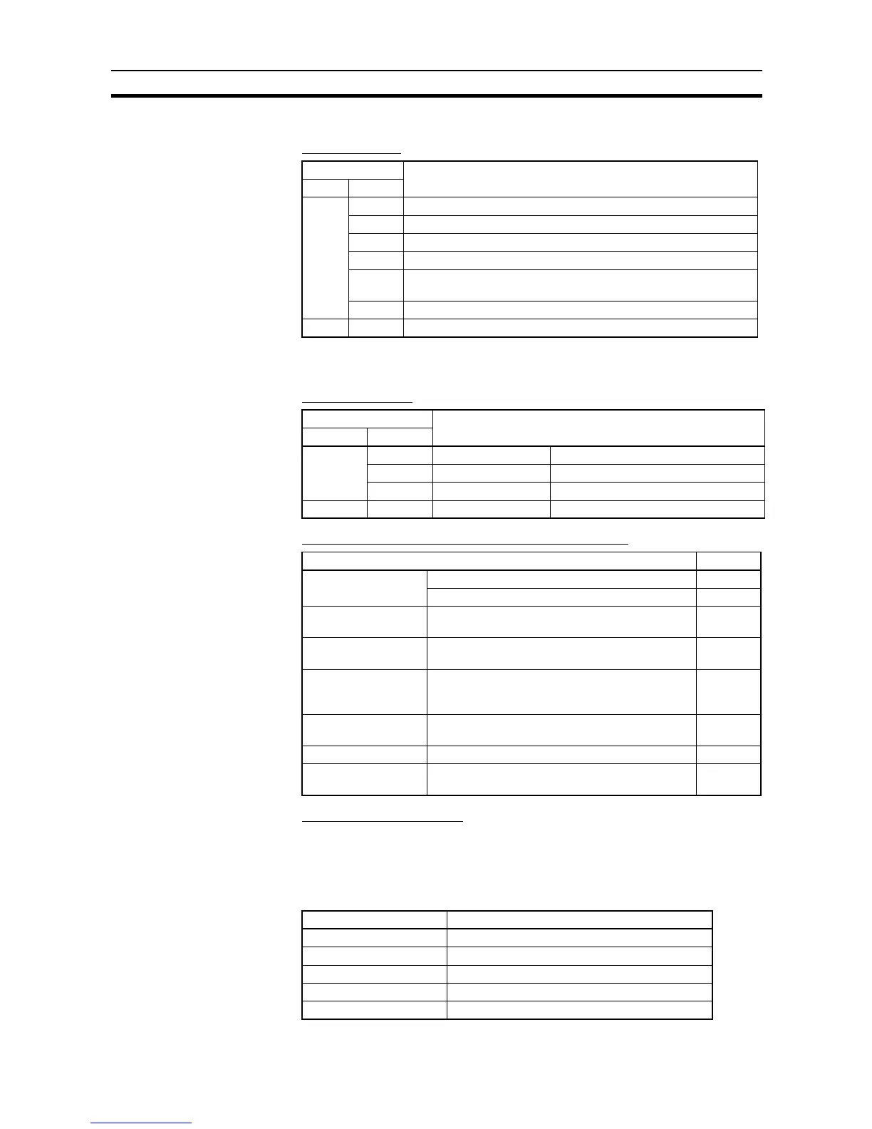
■ I/O Allocations
Input Terminals
Note The high-speed counter inputs are enabled when the
Use high speed counter
0
Option is selected in the PLC Setup’s Built-in Input Tab.
Output Terminals
Auxiliary Area Addresses for High-speed Counter 0
Range Comparison Table
The range comparison table is stored in D10000 to D10039.
■ PLC Setup
Select the
Use high speed counter 0
Option in the PLC Setup’s Built-in Input
Tab.
Input terminal Usage
Word Bit
CIO 0 00 High-speed counter 0 phase-A input (See note.)
01 High-speed counter 0 phase-B input (See note.)
02 Start measurement by pushbutton switch (normal input).
03 Detect trailing edge of measured object (normal input).
04 Detect leading edge of measured object for high-speed counter 0
phase-Z/reset input (see note). Bit status is reflected in A531.00.
05 to 11 Not used. (normal input)
CIO 1 00 to 11 Not used. (normal input)
Output terminal Usage
Word Bit
CIO 100 00 Normal input PL1: Dimension pass output
01 Normal input PL2: Dimension fail output
02 to 07 Normal input Not used.
CIO 101 00 to 07 Normal input Not used.
Function Address
PV storage words Leftmost 4 digits A271
Rightmost 4 digits A270
Range Comparison
Condition Met Flag
Range 1 Comparison Condition Met Flag A274.00
Comparison In-
progress Flag
ON when a comparison operation is being exe-
cuted for the high-speed counter.
A274.08
Overflow/Underflow
Flag
ON when an overflow or underflow has occurred
in the high-speed counter’s PV. (Used only when
the counting mode is set to Linear Mode.)
A274.09
Count Direction Flag 0: Decrementing
1: Incrementing
A274.10
Reset Bit Used for the PV software reset. A531.00
High-speed Counter
Gate Bit
When ON, the counter's PV will not be changed
even if pulse inputs are received for the counter.
A531.08
Item Setting
High-speed counter 0 Use high speed counter 0
Counting mode Linear mode
Circular Max. Count ---
Reset method Software reset
Input Setting Up/Down inputs
 Loading...


