327
Inverter Positioning Section 5-3
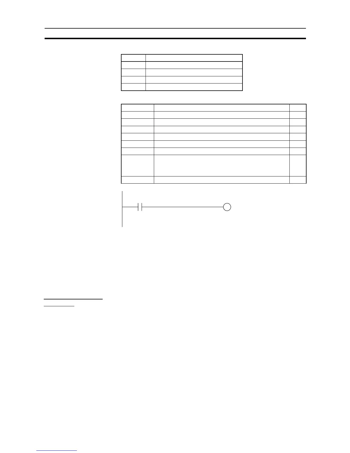
■ Internal Work Addresses
■ Settings Addresses
Modbus Communications
Add the above instructions to the end of the program as a starting condition
for the ladder programming example. For error processing, refer to the ladder
program in
6-3-3 Modbus-RTU Easy Master Function
and to the inverter’s
manual.
5-3-12 Application Example with an Analog Output
Positioning with
Trapezoidal Control
Specifications and
Operation
When start input CIO 1.04 turns ON, 600,000 pulses are output internally for
inverter positioning 0 to turn the motor shaft.
Note Refer to
5-3-7 Determining the Internal Pulse Output Frequency
for the for-
mula to convert the frequency and use the converted internal pulse frequency.
The number of output pulses is calculated from the encoder specifications
and the high-speed counter multiplier.
Address Usage
D1 Bits 00 to 03: Run/Stop Command
D2 Bits 00 to 15: Frequency Command Value
D10 Bits 00 to 03: Forward/Reverse Command
D15 Bit 09: Forward/Reverse Command
Address Usage Data
D32200 Bits 00 to 07: Slave address 01
D32201 Bits 00 to 07: Function code 10
D32202 Bits 00 to 07: Number of communications data bytes 09
D32203 Bits 00 to 15: Register number of write start data 0001
D32204 Bits 00 to 15: Number of data registers to write 0002
D32205 Bits 08 to 15: Number of attached data bytes 04
D32206 Bits 00 to 07: Upper bytes of frequency command value in D2
Bit 08: Run/Stop Command
Bit 09: Forward/Reverse Command
---
D32207 Bits 08 to 15: Lower bytes of frequency command value in D2 ---
A26.00
Operation
Command Flag
A641.00
Modbus-RTU Master Execution Bit