328
Inverter Positioning Section 5-3
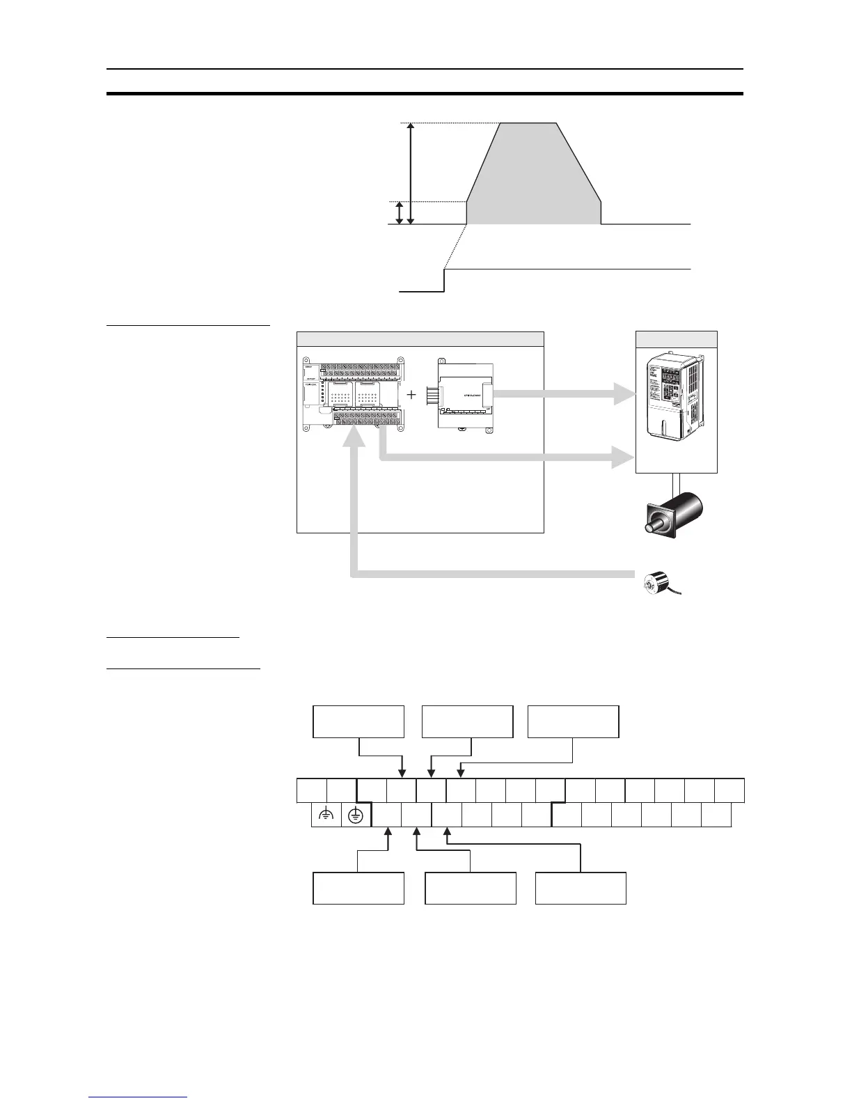
System Configuration
Instructions Used PLS2(887)
Terminal Allocations
■ Error Counter
100 Hz
20,000 Hz
No. of output
pulses: 600,000
Start input
CIO 0.05
Deceleration:
80 Hz/4 ms
Starting
frequency
Target
frequency
Acceleration:
100 Hz/4 ms
Inverter
Standard motor
Encoder
3G3MV
3G3RV
Feedback pulses
Speed Command via Analog Output
SYSMAC
CP1L
L1 L2/N
COM 01 03 05 07 09 11 01 03 05 07 09 11
00 02 04 06 08 10 00 02 04 06 08
10
00 01 02 03 04 06 00 01 03 04 06
COM COM COM COM 05 07 COM 02 COM 05
07
IN
OUT
CH
I OUT1 I OUT3
I OUT2
VOUT1
VOUT2
VOUT3
COM1
COM2
I OUT4
VOUT4
COM4
NC
AG
COM3
OUT
CP1W/CPM1A-DA041
(Analog Output Unit)
CP1L
CP1W/CPM1A-MAD11
(Analog I/O Unit)
Output Bits
· Forward
· Reverse
Current/Voltage
Output
· Frequency
command
L1 L2/N
COM
01
00 02 04 06 08 10 00 02 04 06 08 10
03 05 07 09 11 01 03 05 07 09 11
CIO 0
CIO 1
Error counter 0
Phase B
Error counter 1
Phase B
Error counter 1
Phase Z
Error counter 0
Phase A
Error counter 1
Phase A
Error counter 0
Phase Z