192
High-speed Counters Section 5-1
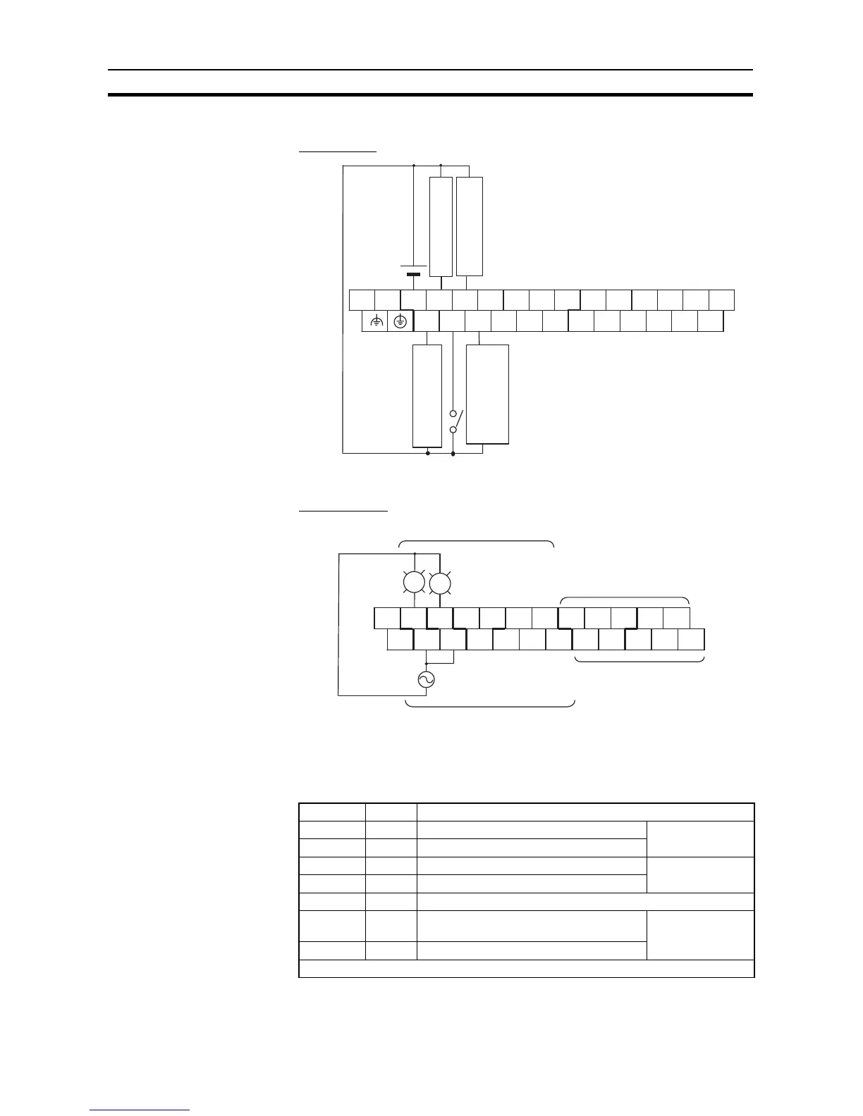
■ I/O Wiring
Input Wiring
Output Wiring
■ Range Comparison Table Settings
The inspection standards data is set in the DM Area with the CX-Programmer.
Even though range 1 is the only range being used, all 40 words must still be
dedicated to the range comparison table.
L1 L2/N COM 01 03 05 07 09 11 01 03 05 07 09 11
00 02 04 06 08 10 00 02 04 06 08 10
Workpiece end
detection
High-speed counter 0
(phase Z)
Workpiece start
detection
High-speed counter 0
(phase B)
Measurement
start switch
High-speed counter 0
(phase A)
Upper Terminal Block
(Example: AC Power
Supply Modules)
+
00 01 06
−
COM
05
07
CIO 100
CIO 101
CIO 100
CIO 101
PL1: OK indicator
PL2: NG indicator
Bottom
terminal block
PL1
PL2
COM
COM
COM
COM COM
03
02
04
06
01 02 03
04
00
05
07
Word Setting Function
D10000 7430 Rightmost 4 digits of range 1 lower limit Lower limit value:
30,000
D10001 0000 Leftmost 4 digits of range 1 lower limit
D10002 765C Rightmost 4 digits of range 1 upper limit Upper limit value:
30,300
D10003 0000 Leftmost 4 digits of range 1 upper limit
D10004 000A Range 1 interrupt task number = 10 (A hex)
D10005 to
D10008
All 0000 Range 2 lower and upper limit values
(Not used and don’t need to be set.)
Range 2 settings
D10009 FFFF Disables range 2.
~
 Loading...


