670
Connections to Serial Communications Option Boards Appendix F
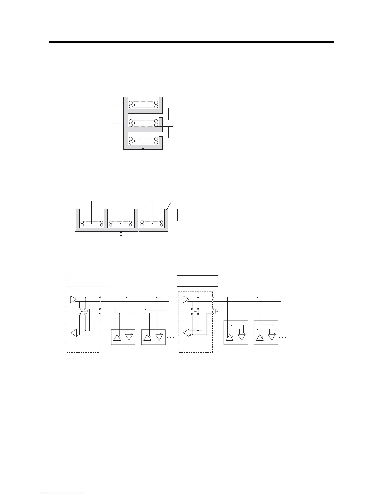
Reducing Electrical Noise for External Wiring
Observe the following precautions when wiring communications cables, PLC power lines, and high-power
lines. When multi-conductor signal cable is being used, avoid using I/O wires and other control wires in the
same cable.
• If wiring racks are running in parallel, allow at least 300 mm between them.
• If the I/O wiring and power cables must be placed in the same duct, they must be shielded from each other
using grounded steel sheet metal.
2-Wire and 4-Wire Connections
The transmission circuits for 2-wire and 4-wire connections are different, as shown in the following diagram.
Note (1) Use the same transmission circuit (2-wire or 4-wire) for all nodes.
(2) Do not use 4-wire connections when the 2/4-wire switch on the Board is set to 2-wire.
Communications
cables
Low-current cables
PLC power supply
and general control
circuit wiring
Power lines
300 mm min.
Ground to 100 Ω or less.
Control cables
Power cables
300 mm min.
Communications
cables
PLC power supply
and general control
circuit wiring
Power lines
200 mm min.
Ground to 100 Ω or less.
Steel sheet metal
Example of 4-Wire
Connections
Example of 2-Wire
Connections
2/4-wire switch
(DPDT)
Option Board
2/4-wire switch
(DPDT)
Option Board
Not connected
Other Unit
Other UnitOther Unit
Other Unit