671
Connections to Serial Communications Option Boards Appendix F
NT-AL001-E Link Adapter Settings
The NT-AL001-E Link Adapter has a DIP switch for setting RS-422A/485 communications conditions. When
connecting the Serial Communications Option Board, refer to the DIP switch settings shown in the following
table.
Note When connecting to a CP-series CPU Unit, turn OFF pin 5 and turn ON pin 6.
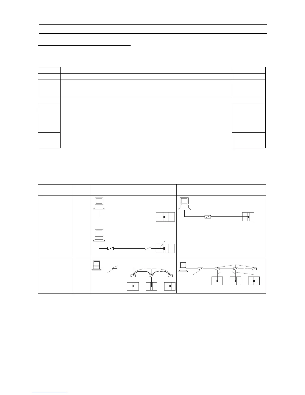
Connections for Host Link Communications
Port connections for Host Link communications are shown in the following table. Up to 32 nodes can be con-
nected for 1:N connections.
Note (1) Four-wire connections must be used for RS-422A/485 connections with Host Link communications.
(2) “Resistance ON” indicates the terminating resistance must be turned ON.
(3) “5-V power” indicates that a 5-V power supply is required for the Link Adapter. Refer to the Link
Adapter manual for details. A 5-V power supply is not required for a Link Adapter connected to an
RS-232C Option Board mounted on the CPU Unit because power is supplied from pin 6 of the con-
nector.
(4) The maximum cable length for RS-232C is 15 m. The RS-232C standard, however, does not cover
baud rates above 19.2 Kbps. Refer to the manual for the device being connected to confirm support.
Pin Function Factory setting
1 Not used. Always set this pin to ON. ON
2 Built-in terminating resistance setting
ON: Connects terminating resistance.
OFF: Disconnects terminating resistance.
ON
3 2/4-wire setting
2-wire: Set both pins to ON.
4-wire: Set both pins to OFF.
OFF
4 OFF
5 Transmission mode (See note.)
Constant transmission: Set both pins to OFF.
Transmission performed when CTS signal in RS-232C interface is at high level:
Set pin 5 to OFF and pin 6 to ON.
Transmission performed when CTS signal in RS-232C interface is at low level:
Set pin 5 to ON and pin 6 to OFF.
ON
6 OFF
Port Config-
uration
Schematic diagram, RS-232C ports Schematic diagram, RS-422A/485 ports
Computer to
PLC: C-mode or
FINS com-
mands
PLC to com-
puter: FINS
commands
1:1
Computer to
PLC: C-mode or
FINS com-
mands
1:N
NT-AL001-E
RS-232C
RS-232C
RS-422A/485
5-V