163
F3SJ-A
User’s Manual
Chapter4 Wiring
Wiring/Installation
E
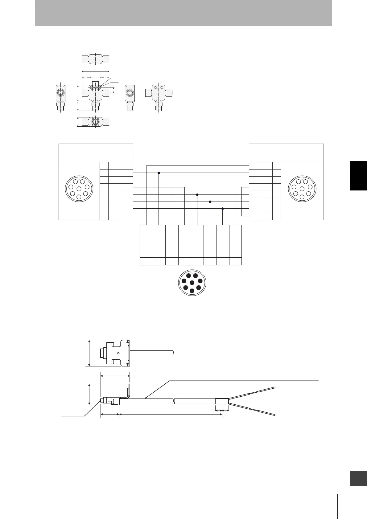
Reduced wiring connector (optional: F39-CN5)
Internal Wiring Diagram (Optional: F39-CN5)
Universal indicator cable: A cable for connection with a commercial indicator
(optional: F39-JJ3N)
24.7
12
13.6 13.6
φ8(SPOTFACING2)
φ4.5
(52)
32.1
10
17.7
18
1
2
3
4
5
6
7
8
1
7
8
2
3
4
5
6
1
7
8
2
3
4
5
6
2
3
8
1
7
6
5
4
1
2
3
4
5
6
7
8
123 4567 8
White
Brown
Black
Yellow
Grey
Pink
Blue
Red
Female Female
White
Brown
Black
Yellow
Grey
Pink
Blue
Red
Male
Connected to emitter's connection cable
and Cable with connectors on both ends
Connected to receiver's connection cable
and Cable with connectors on both ends
0V
+24V DC
Test input
Reset input
Safety
output 1
Safety
output 2
Communication
line (+)
Communication
line (-)
21.4
33.4
3000
(10) (10)
Vinyl insulated round cable: Dia. 6
8-cord (conductor cross section: 0.15mm
2
/insulation diameter: 1mm)
30
24
Connector

 Loading...


