162
Chapter4 Wiring
F3SJ-A
User’s Manual
Wiring/Installation
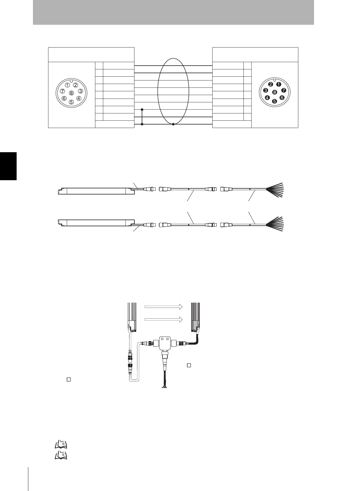
Internal wiring diagram (F39-JDB-L, F39-JDB-D)
If the length of the F39-JCA or F39-JDA single-end connector cable is insufficient, use 1 or more
F39-JCB or F39-JDB double-end connector cables to extend the length, as required.
Connection example
*1 Use only 1 set of F39-JCC. If the cable length is insufficient, use F39-JCB for extension.
Reduced Wiring Connector System
A combination of a double-ended cable for an emitter (F39-JDB-L), a single-ended cable for a
receiver (F39-JDA-D), and a reduced wiring connector (optional: F39-CN5) can be used for a
reduced wiring system.
Cable for reduced wiring (optional: F39-JDBA)
A set of two cables; a double-ended cable for an emitter (F39-JDB) and a single-ended cable for a
receiver (F39-JDA-D). Used in combination with a reduced wiring connector (optional: F39-CN5).
See the following page for details of a double-ended cable for an emitter (F39-JDB-L) and a single-
ended cable for a receiver (F39-JDA-D).
Cable with connectors on both ends p.161
Cable with connector on one end p.159
1
2
3
4
5
6
7
8
1
2
3
4
5
6
7
8
White
Brown
Black*
Yellow
Grey
Pink
Blue
Red
Shield
Female
White
Brown
Black*
Yellow
Grey
Pink
Blue
Red
Shield
Male
Twisted pair wires are white and red, brown and blue, black* and yellow, and grey and pink
* Green for pin #3 wiring color of the double-ended cable F39-JCB.
Connected to connection cable and
Cable with connectors on both ends
Connected to single-end connector cable, Cable
with connectors on both ends, Controller F3SP-B1P,
Reduced Wiring Connector
Emitter
Receiver
Cable is grey
Cable is black
Cable with connectors on both ends
F39-JCB/-JDB
Cable with connector on one end
F39-JCA/-JDA
F39-JCB-L/-JDB-L (Grey) F39-JCA-L/-JDA-L (Grey)
F39-JCB-D/-JDB-D (Black) F39-JCA-D/-JDA-D (Black)
F3SJ
Receiver
F3SJ
Emitter
Cable with connectors on both ends
F39-JD B-L (grey)
Cable with connector on one end
F39-JD A-D (black)
Reduced Wiring
Connector
F39-CN5

 Loading...


