48
Chapter2 Muting System
F3SJ-A
User’s Manual
System Configuration and Functions
Use the PC tool for F3SJ to change following values:
T1min: Muting input time limit value (minimum)
T1max: Muting input time limit value (maximum)
Muting function p.90
To enable the muting function, D2, D3, and d2 must satisfy formulas (3), (4), and (5), respectively.
This distance must prevent the muting function from being enabled by a person passing through the
muting sensors. Also, install the F3SJ and muting sensors so that a workpiece passes through all
muting sensors before the next workpiece arrives at the first muting sensor.
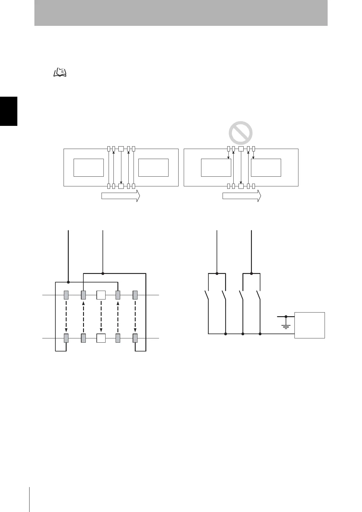
Wiring Diagrams
Workpiece Workpiece Workpiece Workpiece
Moving direction Moving direction
+ 24V DC
0V
A2A1 B2B1
A2
A1 B 2
B1
F3SJ
Muting Input 1
(White)
Muting Input 1
(White)
Muting Input 2(Red)
Muting Input 2(Red)
Power
supply
A1, B1, A2, B2 :
Regressive reflection
photoelectric switch
- NPN Output
- ON when Interrupted
A1, A2, B1, B2 :
N.O contact type switch
Two-wire type muting sensor cannot be used.
*

 Loading...


