The following describes the wiring for the main power supply input terminals and for peripheral equip-
ment.
⚫
Installing molded case circuit breaker
If the inverter’s protective function is activated, the inverter internal circuit may be damaged depend-
ing on the condition.
Be sure to connect the main power supply input terminals (R/L1, S/L2, T/L3) to the power supply via
a molded case circuit breaker (MCCB) according to each inverter.
•
When using multiple inverters, install one MCCB per inverter.
•
Determine the capacity of the MCCB according to the molded case circuit breaker (MCCB) value
shown in the previous table.
•
Determine the time characteristic of the MCCB upon due consideration of the time characteristic
of the inverter’s overheat protection function (150% of the rated output current for 1 minute).
•
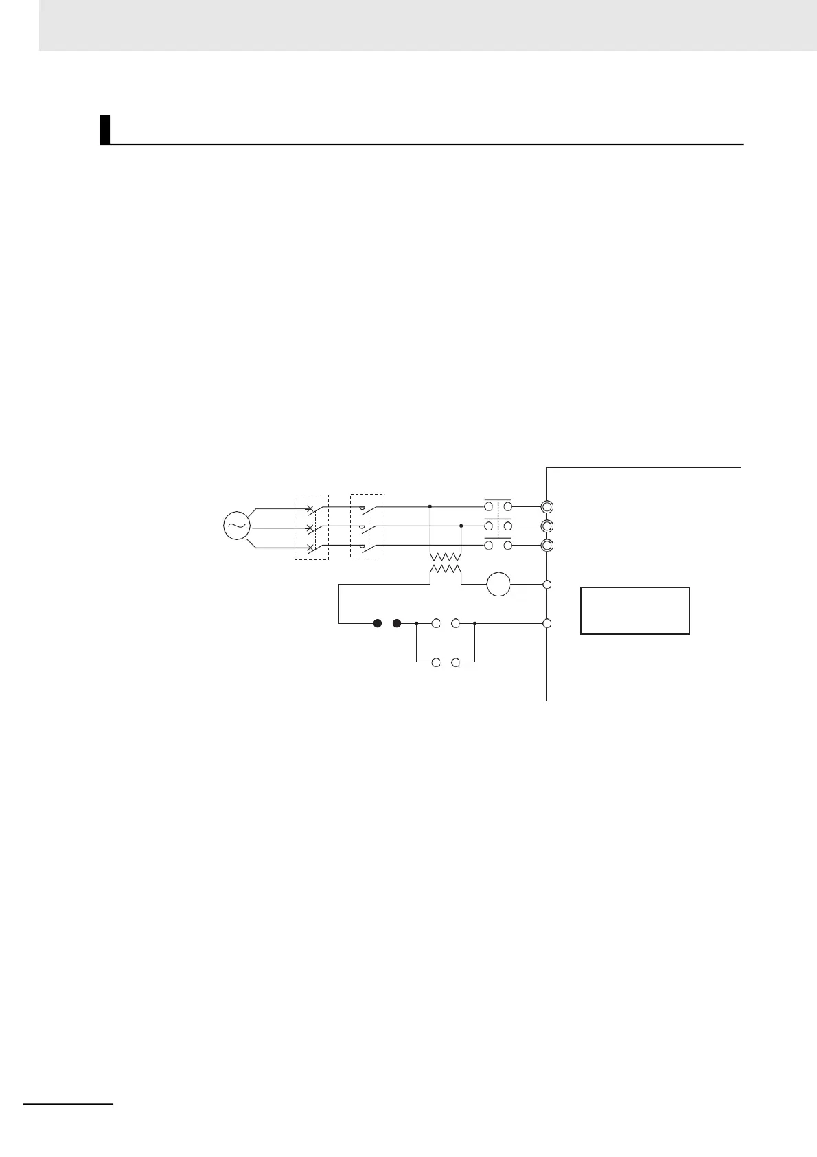
If you must share one MCCB with multiple inverters or other equipment, construct a sequence
that turns OFF the power supply via the alarm output signal, as shown in the figure below.
Inverter
3-phase 200
3-phase 400
*1. For 400-V class, connect a 400/200-V transformer.
*2. Set the Multi-function Relay Output (AL1, AL2) Function Selection (C026) to 05 (AL: Alarm signal).
*3. Set the Multi-function Relay Output (AL1, AL2) Operation Selection (C036) to 00 (NO: NO contact) to
configure the terminal AL2 as NC contact.