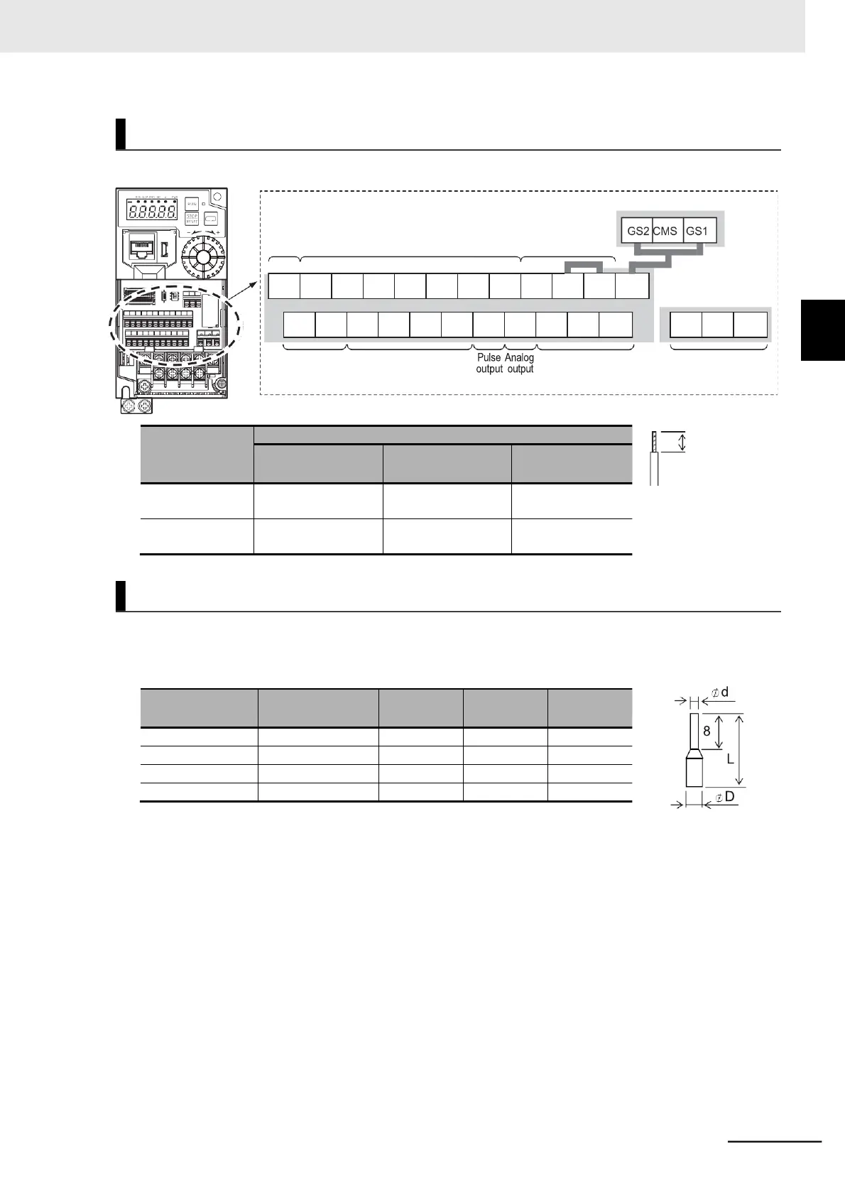
EasyManua.ls Logo

Omron MX2 Series - Page 115

Omron MX2 Series
612 pages
To Next Page IconTo Next Page
To Previous Page IconTo Previous Page
Loading...
2 Design
2 - 37
Multi-function Compact Inverter 3G3MX2-EV2 User’s Manual (I666-E1)
Input power and common
Pulse
Input
Input
Safety function
input and power
supply
Communi-
cations
RS-485
Analog input
and power
supply
Output
Relay output
Arrangement of Control Circuit Terminals
2
2-3 Wiring
2-3-5 Wiring for Control Circuit Terminals
AL2
AL1
AL0
SP
SN
H
O
OI
L
EO
AM
CM2
12
11
Applicable wire
Solid wire mm
2
(AWG)
Stranded wire mm
2
(AWG)
Ferrule mm
2
(AWG)
Control circuit
terminal block
0.2 to 1.5
(AWG24 to 16)
0.2 to 1.0
(AWG24 to 17)
0.25 to 0.75
(AWG24 to 18)
Relay output
terminal block
0.2 to 1.5
(AWG24 to 16)
0.2 to 1.0
(AWG24 to 17)
0.25 to 0.75
(AWG24 to 18)
EA
7
6
5
4
3
2
1
L
PLC
P24
P24S
Wire size
mm
2
(AWG)
Ferrule type
*1
L [mm]
d [mm]
D [mm]
0.25 (24)
AI 0.25-8YE
12.5
0.8
2.0
0.34 (22)
AI 0.34-8TQ
12.5
0.8
2.0
0.5 (20)
AI 0.5-8WH
14
1.1
2.5
0.75 (18)
AI 0.75-8GY
14
1.3
2.8
Recommended Terminal

Table of Contents

Related product manuals