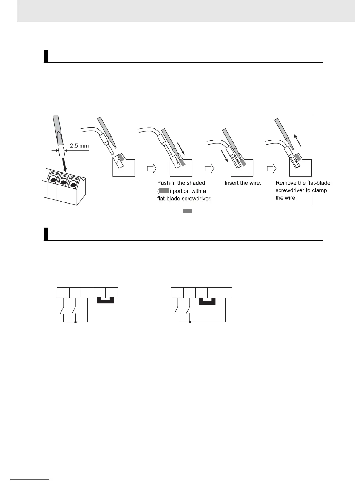
1 Push in the orange colored portion of the terminal with a flat-blade screwdriver (blade
width: 2.5 mm max.) to open the wire insertion hole.
2 With the flat-blade screwdriver pushed in, insert the wire or ferrule into the wire insertion
(round) hole.
3 Remove the flat-blade screwdriver to clamp the wire.
Note To disconnect, pull out the wire with the shaded ( ) portion pushed in with a flat-blade screwdriver.
By factory default, the multi-function input terminals are set to sink logic (NPN).
To change the input control logic to source logic (PNP), remove the short-circuit bar between the termi-
nals P24 and PLC on the control circuit terminal block, and connect it between the terminals PLC and L.
(a) Sink logic (b) Source logic
Short-circuit
ºbar