Multi-function Compact Inverter 3G3MX2-EV2 User’s Manual (I666-E1)
If no problem is found at power-on, the display status will be as follows.
Not lit (Lit during RUN, blinking if the RUN command is input
when the inverter is unable to start operation such as when
the frequency reference is 0 Hz)
RUN key enabled LED indicator
Monitor LED indicator (Hz)
If any problem is found, the display status will be as follows.
Refer to Section 10 Troubleshooting for countermeasures.
RUN key enabled LED indicator
Monitor LED indicator (Hz)
Displays alarm code such as E01 on data display.
(Displayed alarm code differ depending on error condition.)
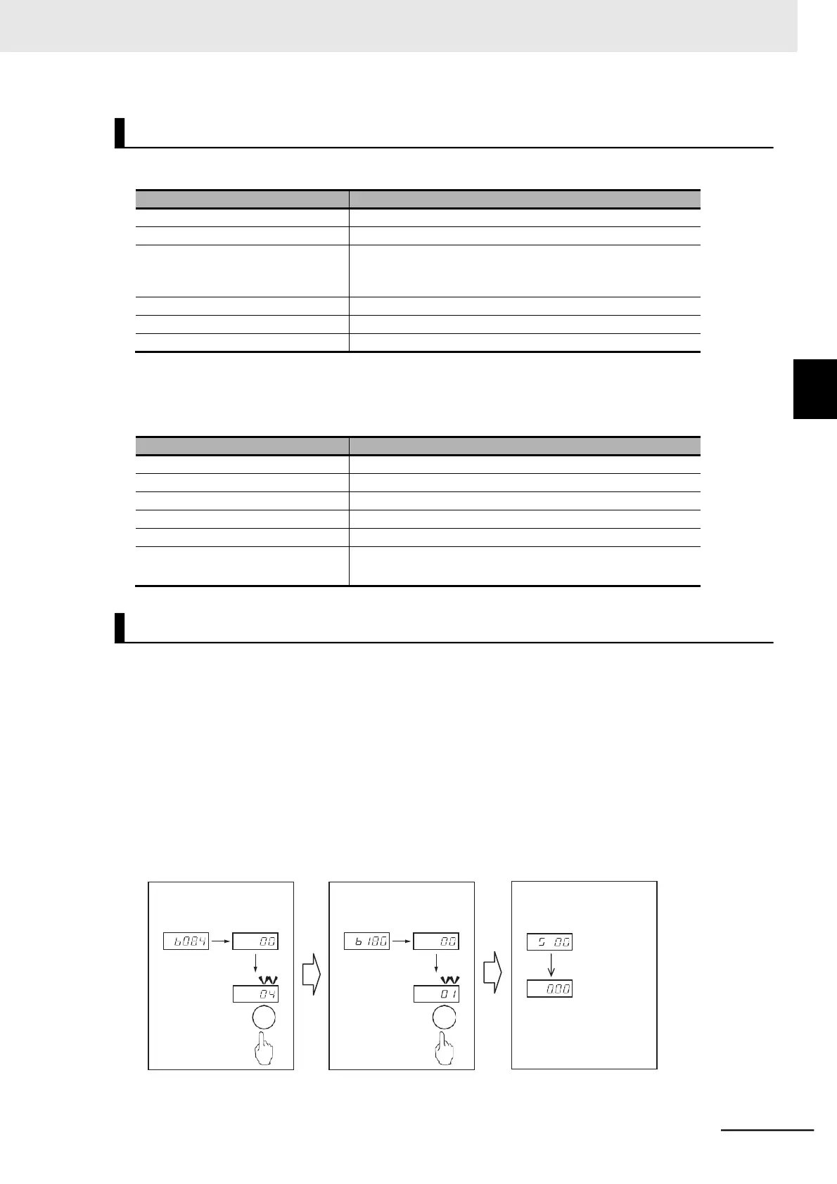
You can initialize the changed parameters and also clear the fault monitor data.
As a measure to prevent inadvertent parameter initialization, the inverter is designed to force the user
to set several parameters to execute initialization.
The following figure shows the steps of complete parameter initialization.
To initialize all the parameters, set the Initialization Target Setting (b094) to 00 (All data).
To initialize the fault monitor and DriveProgramming data in addition to the parameter data, set the Ini-
tialization Selection (b084) to 04.
Set the Initialization Execution (b180) to 01 (Execute initialization) to execute parameter initialization.
For details on parameter initialization, refer to 5-1 Parameter Display and Parameter Initialization on
page 5-3.
3-4 Operation Items for Test Run
Step 2: Set b180 to 01 and
Step 1: Set b084 to 04 and
Step 3: Initialization is com-
pleted when the ini-
tialization display
disappears
Initializing