Multi-function Compact Inverter 3G3MX2-EV2 User’s Manual (I666-E1)
Determination time
(C169)
•
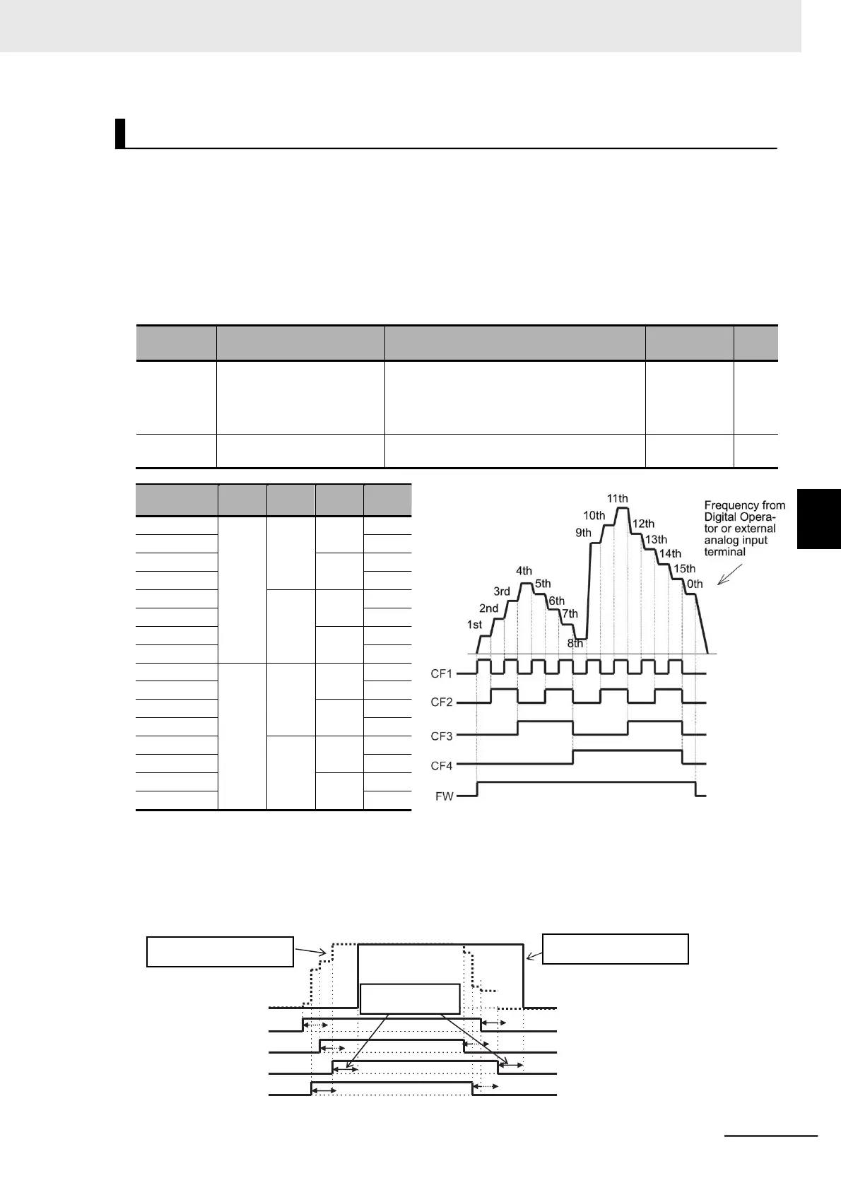
Setting the Multi-function Input 1 to 7 Selection (C001 to C007) to 02 (CF1) to 05 (CF4) enables
the selection of the multi-step speed 0 to 15.
•
Use the Multi-step Speed Reference 1 to 15 (A021 to A035) to set the frequency for the multi-step
speed 1 to 15.
•
Use the 1st/2nd Frequency Reference Selection (A001/A201) to set the 1st/2nd Multi-step Speed
Reference 0 (A020/A220).
Set the 1st/2nd Frequency Reference Selection (A001/A201) to 02 (Digital Operator: F001) to enable
the 1st/2nd Multi-step Speed Reference 0 (A020/A220).
If A001/A201 are set to 01 (Control circuit terminal block: Analog input), the analog input is used as
the frequency reference to set the 1st/2nd Multi-step Speed Reference 0.
Multi-function Input 1 to 7
Selection
02: CF1 (Multi-step speed setting binary 1)
03: CF2 (Multi-step speed setting binary 2)
04: CF3 (Multi-step speed setting binary 3)
05: CF4 (Multi-step speed setting binary 4)
Multi-step Speed/Position
Determination Time
•
For multi-step speed binary operation, the wait time until the inverter recognizes terminal input can be
set in the Multi-step Speed/Position Determination Time (C169). This prevents the transitional status
before terminal input is recognized from being accepted.
•
Input data will be determined if it remains unchanged for the time set in the Multi-step Speed/Position
Determination Time (C169). Note that setting a long determination time results in a slow input
response.
15
11
13
Frequency reference
9
5
1
4
CF1
CF2
CF3
CF4
With zero determination time
(C169)
With determination time
(C169)
5-9 Multi-function Input Settings
5-9-5 Multi-step Speed Operation Function