Multi-function Compact Inverter 3G3MX2-EV2 User’s Manual (I666-E1)
•
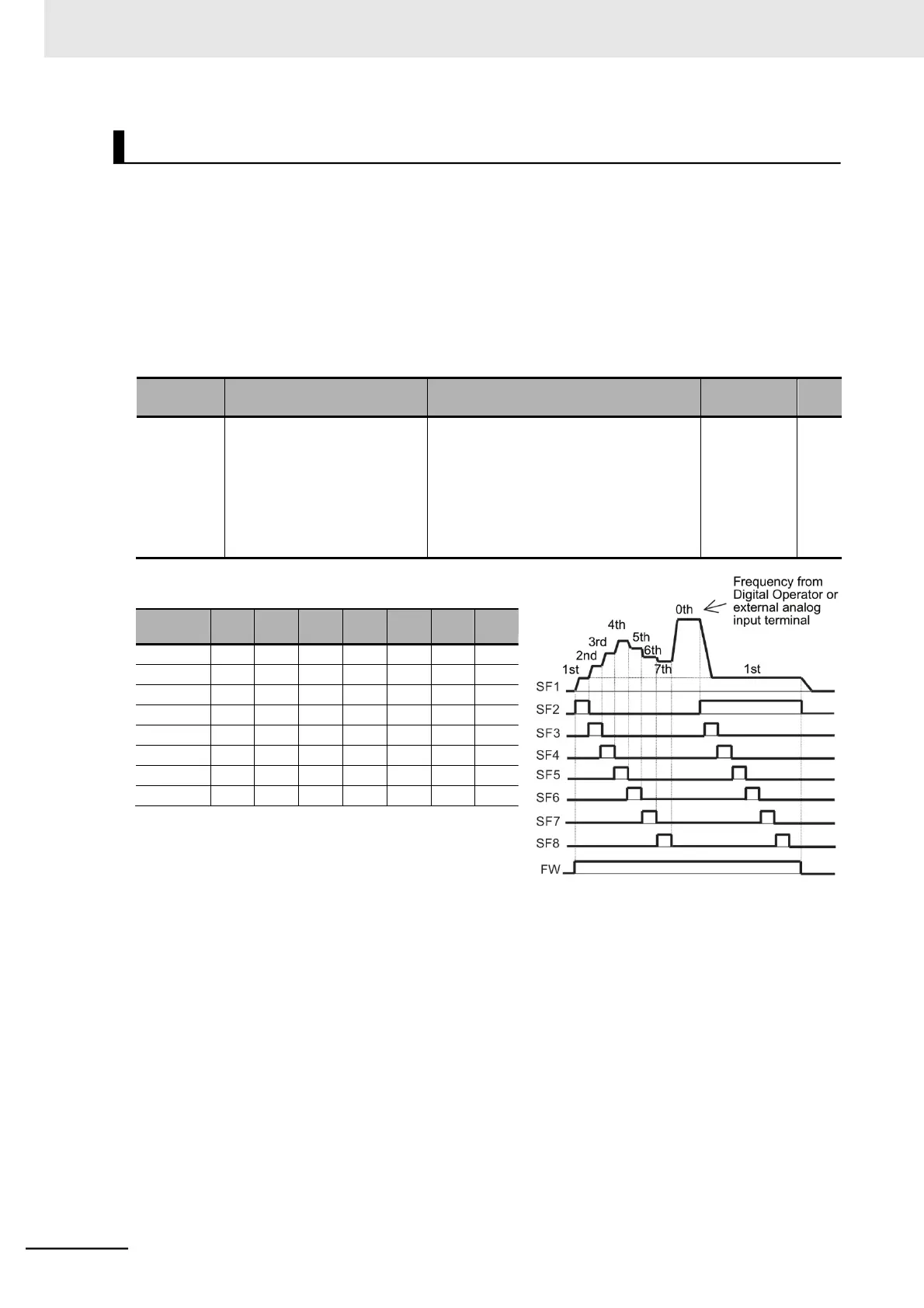
Setting the Multi-function Input 1 to 7 Selection (C001 to C007) to 32 (SF1) to 38 (SF7) enables
the selection of the multi-step speed 0 to 7.
•
Use the Multi-step Speed Reference 1 to 7 (A021 to A027) to set the frequency for SF1 to SF7.
•
Use the 1st/2nd Frequency Reference Selection (A001/A201) to set the 1st/2nd Multi-step Speed
Reference 0 (A020/A220).
Set the 1st/2nd Frequency Reference Selection (A001/A201) to 02 (Digital Operator: F001) to enable
the 1st/2nd Multi-step Speed Reference 0 (A020/A220).
If A001/A201 are set to 01 (Control circuit terminal block: Analog input), the analog input is used as
the frequency reference to set the 1st/2nd Multi-step Speed Reference 0.
Multi-function Input 1 to 7
Selection
32: SF1 (Multi-step speed setting bit 1)
33: SF2 (Multi-step speed setting bit 2)
34: SF3 (Multi-step speed setting bit 3)
35: SF4 (Multi-step speed setting bit 4)
36: SF5 (Multi-step speed setting bit 5)
37: SF6 (Multi-step speed setting bit 6)
38: SF7 (Multi-step speed setting bit 7)
Note When several terminals simultaneously turn ON, prior-
ity is given to the terminal with the smallest number.
“Disabled” in the above table indicates that speed is
selected regardless of the ON/OFF status.