6 Vector Control and Applied Functions
Multi-function Compact Inverter 3G3MX2-EV2 User’s Manual (I666-E1)
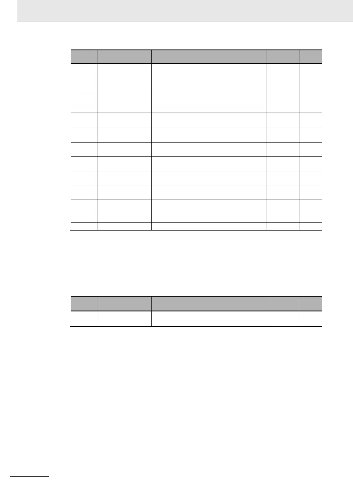
0.1/0.2/0.4/0.55/0.75/1.1/1.5/2.2/3.0/3.7/4.0/
5.5/7.5/11.0/15.0/18.5
Maximum
applicable
motor
capacity
2/4/6/8
10 to 48: Do not set.
30.0 to 1st Maximum Frequency (A004)
1st Base Frequency (A003) to 400.0
1st Motor Rated
Voltage Selection
200-V class: 200/215/220/230/240
400-V class: 380/400/415/440/460/480
0.20 Rated current to 1.00 Rated current
1st Electronic Ther-
mal Level
0.20 Rated current to 1.00 Rated current
DC Injection Brak-
ing Selection
00: Disabled
01: Enabled
02: Enabled (Operates only at set frequency)
*1. The digit shift display mode can be used.
2 Auto-tuning
(1)
Set the Auto-tuning Selection (H001) to 01 (Enabled: No motor rotation).
The available setting for PM motor auto-tuning is 01 (Enabled: No motor rotation) only. The
setting “02 (Enabled: Motor rotation)” is not displayed.
00: Disabled
01: Enabled (No motor rotation)
(2)
Turn ON the RUN command based on the setting in the 1st RUN Command Selection
(A002).
Turing ON the RUN command causes the inverter to start automatic operation, during
which auto-tuning is executed in the following sequence.
If auto-tuning is completed successfully, the auto-tuning result will be set to the parameters
H111 to H113.
1)
Initial pole position estimation (Motor does not rotate.)
2)
1st DC excitation (Motor does not rotate.)
3)
1st AC excitation (Motor does not rotate.)
4)
2nd AC excitation (Motor does not rotate.)