6 Vector Control and Applied Functions
Multi-function Compact Inverter 3G3MX2-EV2 User’s Manual (I666-E1)
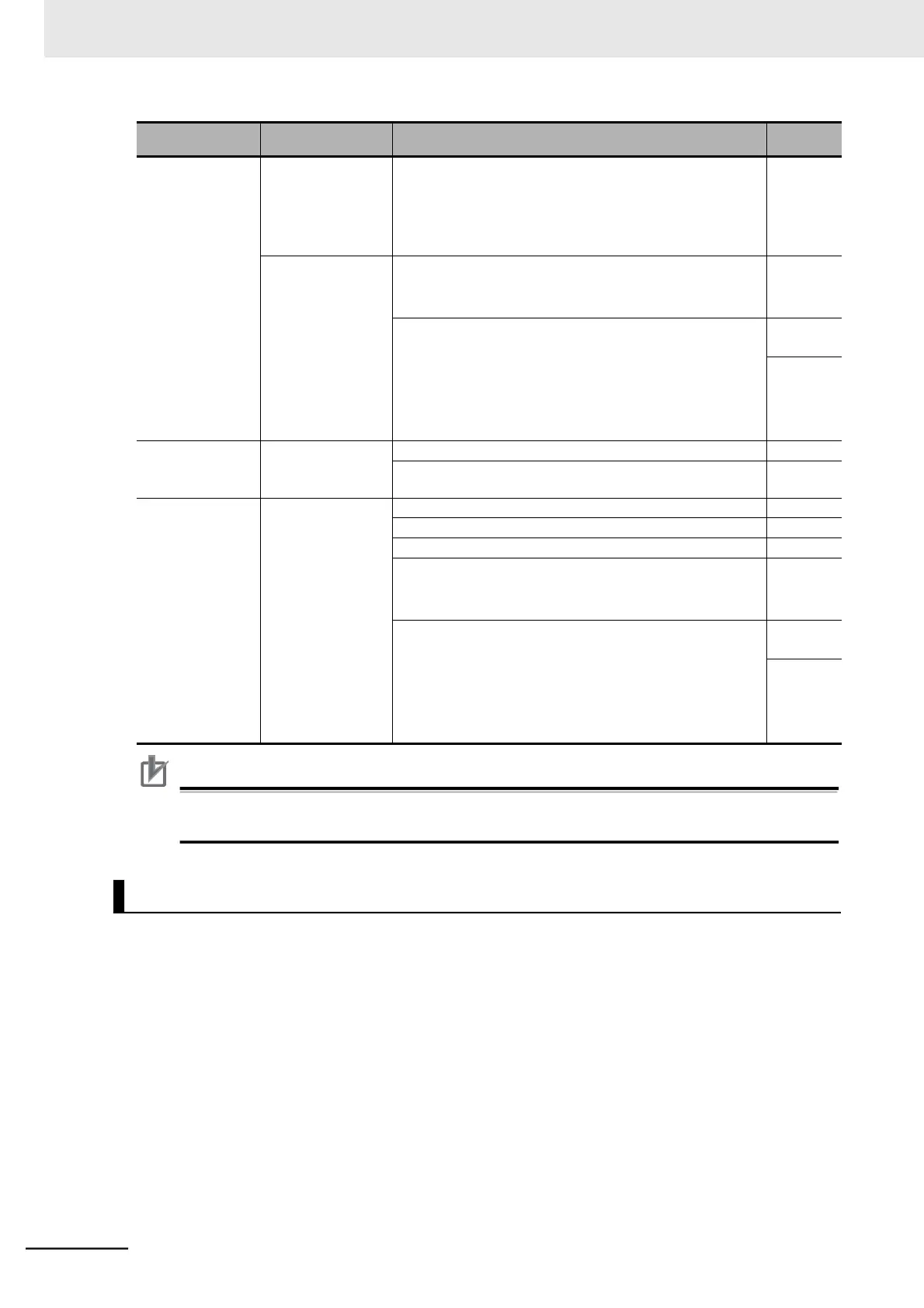
PM Motor Mini-
mum Frequency
(H121) or lower
If the motor rotation is unstable during startup, increase the
motor starting time.
However, setting this parameter to an excessively large
value may cause an overload. Check the value in the Elec-
tronic Thermal Load Rate Monitor (d104).
Motor is hunting or
vibrating.
Finely adjust the motor parameters for PM motor control.
Decrease the PM Motor Parameter R value gradually,
down to 70% of the set value.
Increase the PM Motor Parameter Ld value gradually, up to
130% of the set value.
Increase the PM Motor Parameter Lq value gradually, up to
130% of the set value.
* Be sure to adjust this parameter so that Ld is equal to or
less than Lq.
Around PM Motor
Minimum Fre-
quency (H121)
A shock or overcur-
rent trip occurs.
Increase the PM Motor Speed Response value.
Decrease the minimum frequency of the PM motor.
PM Motor Mini-
mum Frequency
(H121) or higher
Motor is hunting or
vibrating.
Decrease the PM Motor Speed Response value.
Increase the PM Motor No-Load Current value.
Increase the Carrier Frequency, if too low.
Finely adjust the motor parameters for PM motor control.
Decrease the PM Motor Parameter R value gradually,
down to 70% of the set value.
Increase the PM Motor Parameter Ld value gradually, up to
130% of the set value.
Increase the PM Motor Parameter Lq value gradually, up to
130% of the set value.
* Be sure to adjust this parameter so that Ld is equal to or
less than Lq.
Precautions for Correct Use
Increasing the PM Motor Starting Current (H117) too much causes an overload. Alternatively,
doing so causes automatic carrier reduction depending on the set value.
The PM motor initial pole position estimation function estimates the magnetic pole position of the PM
motor in a stop state and causes the inverter to start its output according to the estimated magnetic pole
position.
Set PM motor parameters according to 6-8-4 Offline Auto-tuning for PM Motor Parameters on page
6-59 or 6-8-5 PM Motor Parameter Settings on page 6-62 in advance, because the function uses these
settings to estimate the magnetic pole position of the PM motor.
•
Set the PM Motor Starting Method Selection (H123) to 01 (Initial pole position estimation enabled).
•
The PM motor initial pole position estimation function causes the inverter to output a high-frequency
detection signal to estimate the magnetic pole position. This means that the estimated position is
more accurate as the values set in the PM Motor Initial Pole Position Estimation 0V Waiting Times
(H131)/PM Motor Initial Pole Position Estimation Detection Waiting Times (H132) or in the PM Motor
Initial Pole Position Estimation Detection Times (H133) is larger.
However, the motor staring time becomes longer in proportion to the set PM Motor Initial Pole Posi-
tion Estimation 0V Waiting Times.
PM Motor Initial Pole Position Estimation