2
1-1 Overview
A PC (Programmable Controller) is basically a CPU (Central Processing Unit)
containing
a program and connected to input and
output (I/O) devices. The pro
-
gram
controls the PC so
that when an input signal from an input device turns ON,
the
appropriate response is made. The response normally involves turning ON
an
output signal to some sort of output device. The input devices could be photo
-
electric
sensors, pushbuttons
on control panels, limit switches, or any other de
-
vice that can produce a signal that can be input into the PC. The output devices
could be solenoids, switches activating indicator lamps, relays turning on mo-
tors,
or any other devices that can be activated by signals output from the PC.
For
example, a sensor detecting a passing product turns ON an input
to the PC.
The
PC responds by turning ON an output that activates a pusher that pushes
the
product onto another conveyor for further processing. Another sensor
, posi
-
tioned
higher than the first, turns ON a dif
ferent input to indicate that the product
is
too tall. The PC responds by turning on another pusher positioned before the
pusher mentioned above to push the too-tall product into a rejection box.
Although
this example involves only two inputs and two outputs, it is typical of the
type of control operation that PCs can achieve. Actually even this example is
much
more complex than it may at first appear because of the timing that would
be required, i.e., “How does the PC know when to activate each pusher?” Much
more
complicated operations, however
, are also possible. The problem is how
to get the desired control signals from available inputs at appropriate times.
To
achieve proper control, the C200HS uses a form of PC logic called ladder-dia
-
gram
programming. This manual is written to explain ladder-diagram program
-
ming and to prepare the reader to program and operate the C200HS.
1-2 The Origins of PC Logic
PCs
historically originate in relay-based control
systems. And although the inte
-
grated
circuits and internal logic of the PC have taken the place of the discrete
relays,
timers,
counters, and other such devices, actual PC operation proceeds
as if those discrete devices were still in place. PC control, however, also pro-
vides
computer capabilities and accuracy to achieve a great deal more flexibility
and reliability than is possible with relays.
The symbols and other control concepts used to describe PC operation also
come from relay-based control and form the basis of the ladder-diagram pro-
gramming
method. Most of the terms used to describe these symbols and
con
-
cepts, however, have come in from computer terminology.
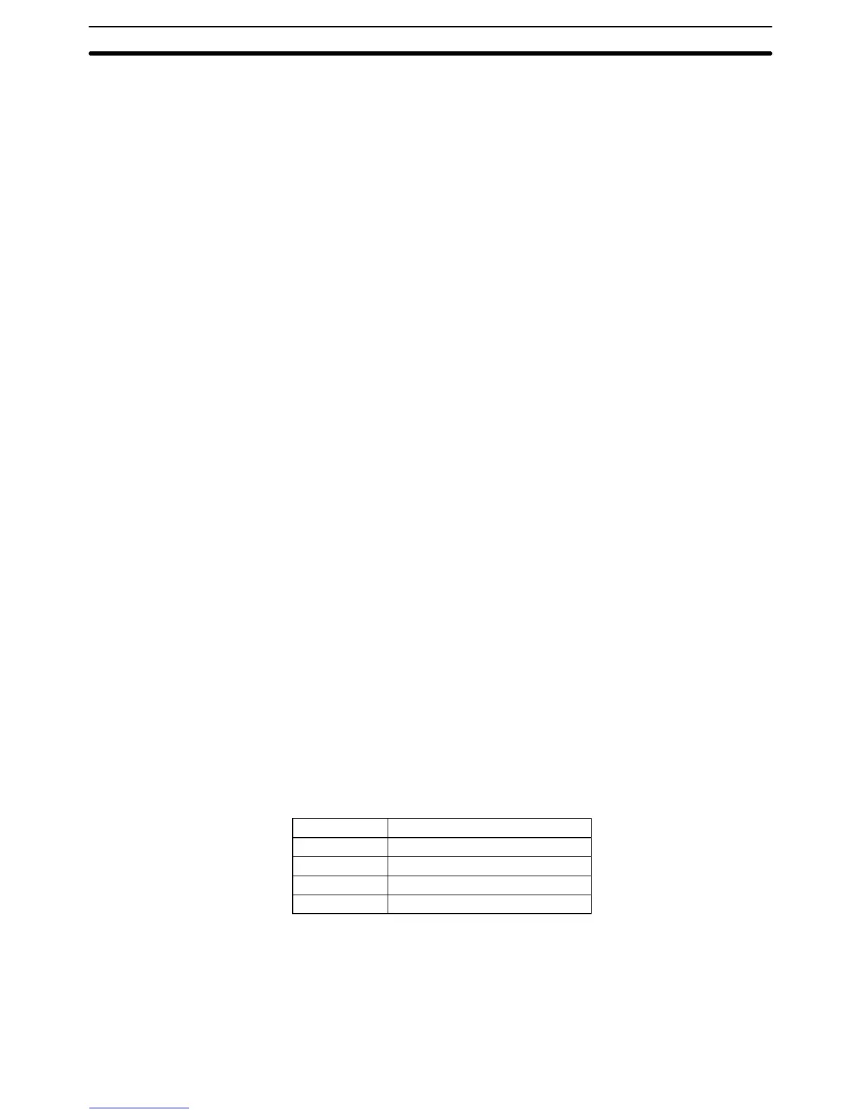
Relay vs. PC Terminology The
terminology
used throughout this manual is somewhat dif
ferent from relay
terminology, but the concepts are the same.
The following table shows the relationship between relay terms and the PC
terms used for OMRON PCs.
Relay term PC equivalent
contact input or condition
coil output or work bit
NO relay normally open condition
NC relay normally closed condition
Actually
there is not a total equivalence between these terms. The term
condi
-
tion
is only used to describe ladder diagram programs in general
and is specifi
-
cally
equivalent to one of certain set of basic instructions. The terms input
and
output are not used in programming per se, except in reference to I/O bits that
are assigned to input and output signals coming into and leaving the PC. Nor-
mally
open conditions
and normally closed conditions are explained in
4-4 Basic
Ladder Diagrams.
The Origins of PC Logic Section 1-2