54
3-5-11 Power OFF Counter
AR
23 provides in 4-digit BCD the number of times that the PC power has been
turned
of
f. This counter can be reset as necessary using the PV
Change 1 op
-
eration
from the Programming Console. (Refer to
7-1-4 Hexadecimal/BCD
Data
Modification
for details.) The Power OFF Counter is refreshed every time power
is turned on.
3-5-12 Cycle Time Flag
AR 2405 turns ON when the cycle time set with SCAN(18) is shorter than the
actual cycle time.
AR 2405 is refreshed every cycle while the PC is in RUN or MONITOR mode.
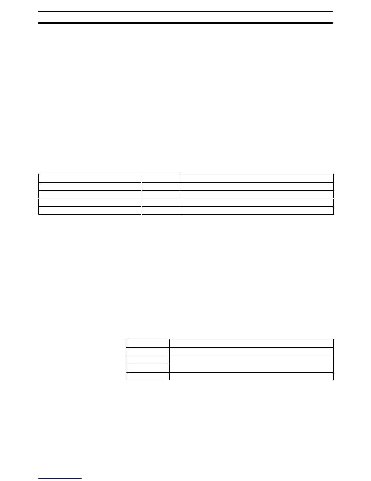
3-5-13 Link Unit Mounted Flags
The following flags indicate when the specified Link Units are mounted to the
Racks.
(Refer to
3-5-14
CPU-mounting Device Mounted
Flag
for CPU-mounting
Host Link Units.) These flags are refreshed every cycle.
Name Bit Link Unit
PC Link Unit Level 1 AR 2411 PC Link Unit in operating level 1
PC Link Unit Level 0 AR 2412 PC Link Unit in operating level 0
Rack-mounting Host Link Unit Level 1 AR 2413 Rack-mounting Host Link Unit in operating level 1
Rack-mounting Host Link Unit Level 0 AR 2414 Rack-mounting Host Link Unit in operating level 0
3-5-14 CPU-mounting Device Mounted Flag
AR 2415 turns ON when any device is mounted directly to the CPU. This in-
cludes CPU-mounting Host Link Units, Programming Consoles, and Interface
Units. This flag is refreshed every cycle.
3-5-15 FPD Trigger Bit
AR
2508 is used to adjust the monitoring time of FPD(––) automatically
. Refer to
5-25-12 FAILURE POINT DETECT – FPD(––) for details.
3-5-16 Data Tracing Flags and Control Bits
The
following control bits and flags
are used during data tracing with TRSM(45).
The Tracing Flag will be ON during tracing operations. The Trace Completed
Flag will turn ON when enough data has been traced to fill Trace Memory.
Bit Name
AR
2512
Trace Completed Flag
AR 2513 Tracing Flag
AR 2514 Trace Trigger Bit (writeable)
AR 2515 Sampling Start Bit (writeable)
Note Refer to 5-25-3 TRACE MEMORY SAMPLING – TRSM(45) for details.
3-5-17 Cycle Time Indicators
AR
26 contains the maximum cycle time that has occurred since program execu
-
tion was begun. AR 27 contains the present cycle time.
Both
times are to tenths of a millisecond in 4-digit BCD (000.0 ms to 999.9 ms),
and are refreshed every cycle.
AR Area Section 3-5