EasyManua.ls Logo

Omron SYSMAC C200HS User Manual

Omron SYSMAC C200HS
503 pages
To Next Page IconTo Next Page
To Previous Page IconTo Previous Page
Page #229 background imageLoading...
Page #229 background image
219
5-20 Binary Calculations
Binary calculation instructions — ADB(50), SBB(51), MLB(52), DVB(53),
ADBL(––),
SBBL(––), MBS(––), MBSL(––), DBS(––), and DBSL(––) — perform
arithmetic operations on hexadecimal data.
Four of these instructions (ADB(50), SBB(51), ADBL(––), and SBBL(––)) can
act
on
both normal and signed data, two (MLB(52) and DVB(53)) act only on nor
-
mal
data, and four (MBS(––),
MBSL(––), DBS(––), and DBSL(––)) act only on
signed binary data.
The
addition and subtraction instructions include CY in the calculation as well as
in
the result. Be sure to clear
CY if its previous status is not required in the calcu
-
lation,
and to use
the result placed in CY
, if required, before it is changed by the
execution
of any other instruction. STC(40) and CLC(41) can be used to control
CY. Refer to 5-19 BCD Calculations.
Signed
binary
addition and subtraction instructions use the underflow and over
-
flow flags (UF and OF) to indicate whether the result exceeds the acceptable
range for 16-bit or 32-bit signed binary data. Refer to page 29 for details on
signed binary data.
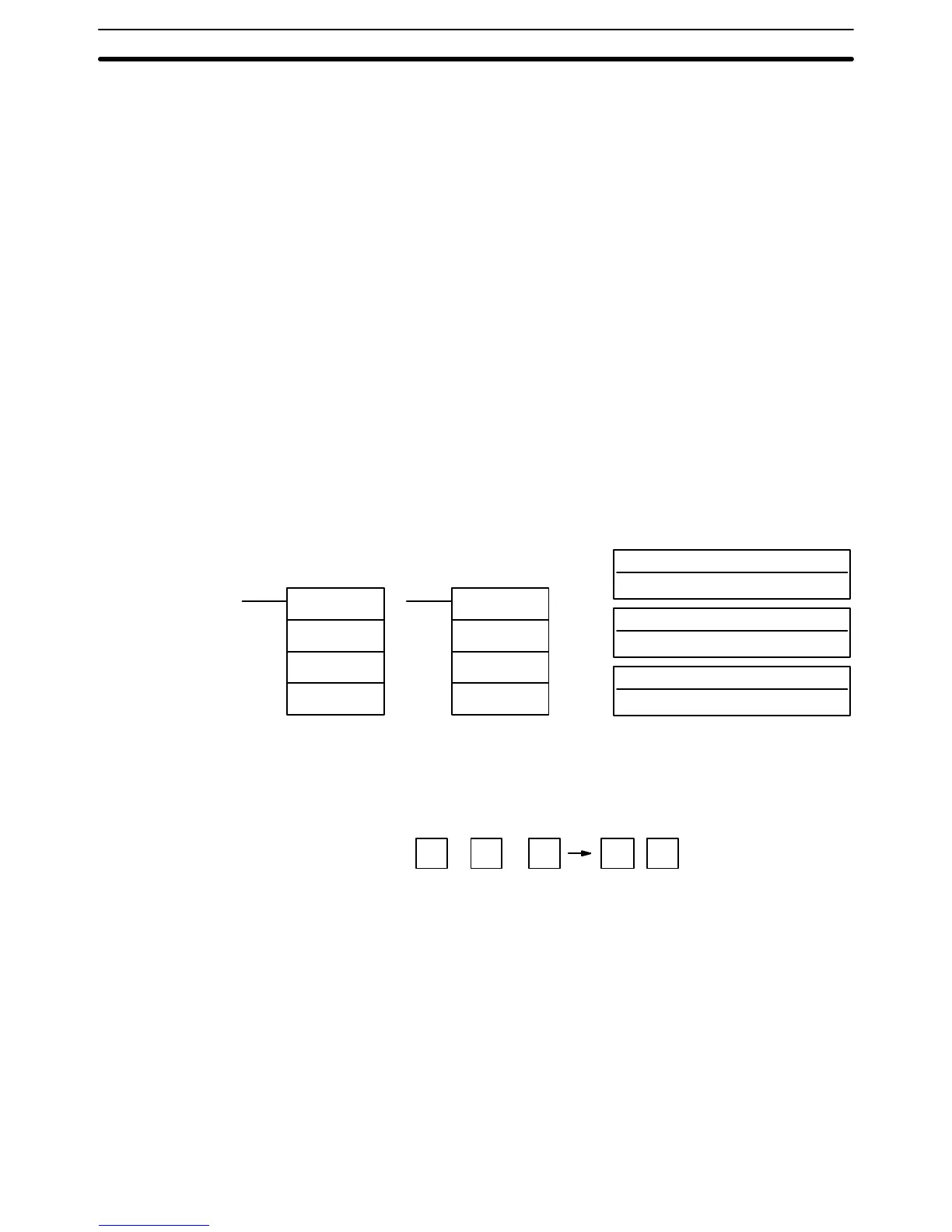
5-20-1 BINARY ADD – ADB(50)
Au: Augend word (binary)
IR, SR, AR, DM, HR, TC, LR, #
Ad: Addend word (binary)
IR, SR, AR, DM, HR, TC, LR, #
Ladder Symbols
Operand Data Areas
R: Result word
IR, SR, AR, DM, HR, LR
ADB(50)
Au
Ad
R
@ADB(50)
Au
Ad
R
Description When the execution condition is OFF, ADB(50) is not executed. When the ex-
ecution condition is ON, ADB(50) adds the contents of Au, Ad, and CY, and
places the result in R. CY will be set if the result is greater than FFFF.
Au + Ad + CY CY R
ADB(50)
can also be used
to add signed binary data. The underflow and over
-
flow
flags (SR 25404 and SR 25405) indicate
whether the result has exceeded
the
lower or upper limits of the
16-bit signed binary data range. Refer to page
29
for details on signed binary data.
Flags ER: Indirectly
addressed
DM word is non-existent. (Content of
:
DM word is
not BCD, or the DM area boundary has been exceeded.)
CY: ON when the result is greater than FFFF.
EQ: ON when the result is 0.
OF: ON when the result exceeds +32,767 (7FFF).
UF: ON when the result is below –32,768 (8000).
Binary Calculations Section 5-20

Table of Contents

Other manuals for Omron SYSMAC C200HS

Questions and Answers:

Omron SYSMAC C200HS Specifications

General IconGeneral
ModelC200HS
ManufacturerOmron
SeriesSYSMAC
Humidity10 to 90% RH (non-condensing)
Programming LanguageLadder logic
Program MemoryRAM/EPROM/EEPROM
Communication ProtocolsSYSMAC LINK, SYSMAC NET
Communication PortsRS-232C, RS-422
Power Supply100-240V AC, 24V DC
Operating Temperature0 to 55°C
Vibration Resistance10 to 57 Hz, 0.075mm amplitude

Summary

SECTION 1 Introduction

1-1 Overview

Provides a general introduction to Programmable Controllers (PCs), their operation, and programming concepts.

SECTION 2 Hardware Considerations

2-1 CPU Components

Details the main components of the C200HS CPU, including indicators, fuses, and connection ports.

SECTION 3 Memory Areas

SECTION 4 Writing and Inputting the Program

4-4 Basic Ladder Diagrams

Introduces fundamental concepts of ladder diagram programming, including rungs, conditions, and instructions.

4-7 Inputting, Modifying, and Checking the Program

Details the procedures for entering, editing, checking, and debugging programs using the Programming Console.

SECTION 5 Instruction Set

5-8 Ladder Diagram Instructions

Details fundamental instructions used in ladder diagrams like LOAD, AND, OR, and their variations.

SECTION 6 Program Execution Timing

6-4 I/O Response Time

Details the time taken for the PC to respond to input signals and produce output signals.

SECTION 7 Program Monitoring and Execution

7-1 Monitoring Operation and Modifying Data

Covers procedures for observing and modifying PC data like bits, words, timers, and counters.

SECTION 8 Communications

8-2 Parameters for Host Link and RS-232C Communications

Details essential PC Setup parameters required for enabling Host Link and RS-232C communications.

SECTION 10 Troubleshooting

10-4 Error Messages

Lists common error messages, their probable causes, and possible corrections for diagnosing system problems.

SECTION 11 Host Link Commands

11-3 Host Link Commands

Details the various commands used for host computer communication with the C200HS PC.

Appendix B Programming Instructions

Appendix D Memory Areas

Appendix E PC Setup

RS-232C Port Settings (DM 6645 to DM 6649)

Details the specific parameters for configuring the RS-232C port, essential for communication setup.

Related product manuals