EasyManua.ls Logo

Omron SYSMAC C200HS User Manual

Omron SYSMAC C200HS
503 pages
To Next Page IconTo Next Page
To Previous Page IconTo Previous Page
Page #301 background imageLoading...
Page #301 background image
291
Example In
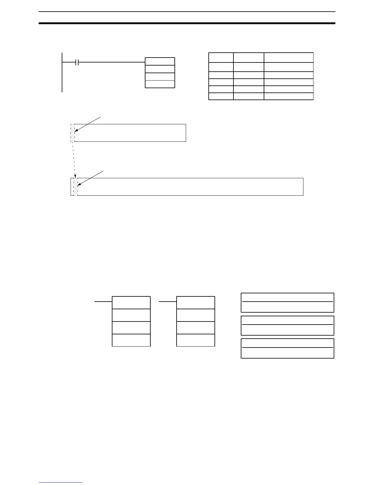
the following example, the 100 word range from
DM 7000 through DM 7099 is
copied to DM 0010 through DM 0109 when IR 00001 is ON.
@XDMR(––)
#7000
#0100
00001
DM 0010
Address Instruction Operands
00000 LD 00001
00001 @XDMR(––)
# 0100
# 7000
DM 0010
DM
7000
DM 9999
DM 7000 to DM 7099
DM 0000 DM 6143
DM 0010 to DM 0109
5-26 Network Instructions
The
SYSMAC NET Link/SYSMAC LINK instructions are used for communicat
-
ing
with other PCs linked through
the SYSMAC NET Link System or SYSMAC
LINK System. These instructions are applicable to the C200H-CPU31-E and
CPU33-E only.
5-26-1 NETWORK SEND – SEND(90)
S: Source beginning word
IR, SR, AR, DM, HR, TC, LR
D: Destination beginning word
IR, AR, DM, HR, TC, LR
Operand Data Areas
C: First control data word
IR, AR, DM, HR, TC, LR
Ladder Symbols
SEND(90)
S
D
C
@SEND(90)
S
D
C
Limitations Can
be performed with the CPU31-E/33-E only
. C through C+2 must be
within
the
same data area and must be within the values specified below
. T
o be able to
use
SEND(90), the system must have a SYSMAC NET Link or SYSMAC LINK
Unit mounted.
Description When
the execution condition is OFF
, SEND(90) is not executed. When the exe
-
cution condition is ON, SEND(90) transfers data beginning at word S, to ad-
dresses
specified by D in the designated node on the SYSMAC NET Link/SYS
-
MAC
LINK System. The
control words, beginning with C, specify the number of
words
to be sent, the destination node, and
other parameters. The contents of
the
control data depends on whether a transmission is
being sent in a SYSMAC
NET Link System or a SYSMAC LINK System.
Network Instructions Section 5-26

Table of Contents

Other manuals for Omron SYSMAC C200HS

Questions and Answers:

Omron SYSMAC C200HS Specifications

General IconGeneral
ModelC200HS
ManufacturerOmron
SeriesSYSMAC
Humidity10 to 90% RH (non-condensing)
Programming LanguageLadder logic
Program MemoryRAM/EPROM/EEPROM
Communication ProtocolsSYSMAC LINK, SYSMAC NET
Communication PortsRS-232C, RS-422
Power Supply100-240V AC, 24V DC
Operating Temperature0 to 55°C
Vibration Resistance10 to 57 Hz, 0.075mm amplitude

Summary

SECTION 1 Introduction

1-1 Overview

Provides a general introduction to Programmable Controllers (PCs), their operation, and programming concepts.

SECTION 2 Hardware Considerations

2-1 CPU Components

Details the main components of the C200HS CPU, including indicators, fuses, and connection ports.

SECTION 3 Memory Areas

SECTION 4 Writing and Inputting the Program

4-4 Basic Ladder Diagrams

Introduces fundamental concepts of ladder diagram programming, including rungs, conditions, and instructions.

4-7 Inputting, Modifying, and Checking the Program

Details the procedures for entering, editing, checking, and debugging programs using the Programming Console.

SECTION 5 Instruction Set

5-8 Ladder Diagram Instructions

Details fundamental instructions used in ladder diagrams like LOAD, AND, OR, and their variations.

SECTION 6 Program Execution Timing

6-4 I/O Response Time

Details the time taken for the PC to respond to input signals and produce output signals.

SECTION 7 Program Monitoring and Execution

7-1 Monitoring Operation and Modifying Data

Covers procedures for observing and modifying PC data like bits, words, timers, and counters.

SECTION 8 Communications

8-2 Parameters for Host Link and RS-232C Communications

Details essential PC Setup parameters required for enabling Host Link and RS-232C communications.

SECTION 10 Troubleshooting

10-4 Error Messages

Lists common error messages, their probable causes, and possible corrections for diagnosing system problems.

SECTION 11 Host Link Commands

11-3 Host Link Commands

Details the various commands used for host computer communication with the C200HS PC.

Appendix B Programming Instructions

Appendix D Memory Areas

Appendix E PC Setup

RS-232C Port Settings (DM 6645 to DM 6649)

Details the specific parameters for configuring the RS-232C port, essential for communication setup.

Related product manuals