158
Description When
the execution condition is OFF
, ASFT(17) does nothing and the program
moves
to the next instruction. When the execution condition is ON, ASFT(17) is
used to create and control a reversible asynchronous word shift register be-
tween
St and E. This register only shifts words when the next word in the
register
is
zero, e.g.,
if no words in the register contain zero, nothing is shifted. Also, only
one word is shifted for each word in the register that contains zero. When the
contents
of a word are shifted to the next word, the original word’
s contents
are
set
to zero. In essence, when the register is shifted, each zero word in the regis
-
ter trades places with the next word. (See Example below.)
The
shift direction (i.e. whether the “next word” is
the next higher or the next low
-
er
word) is designated in C. C is also used to reset the register
. All of any portion
of the register can be reset by designating the desired portion with St and E.
Control Word Bits
00 through 12 of C are not used.
Bit 13 is the shift direction: turn bit 13 ON to
shift
down (toward lower addressed words) and OFF to shift up (toward higher
addressed words). Bit 14 is the Shift Enable Bit: turn bit 14 ON to enable shift
register
operation according to bit 13 and OFF to disable the register
. Bit 15 is the
Reset bit: the register will be reset (set to zero) between St and E when
ASFT(17) is executed with bit 15 ON. Turn bit 15 OFF for normal operation.
Flags ER: The St and E words are in different areas, or St is greater than E.
Indirectly
addressed DM word
is non-existent. (Content of
∗
DM word is
not BCD, or the DM area boundary has been exceeded.)
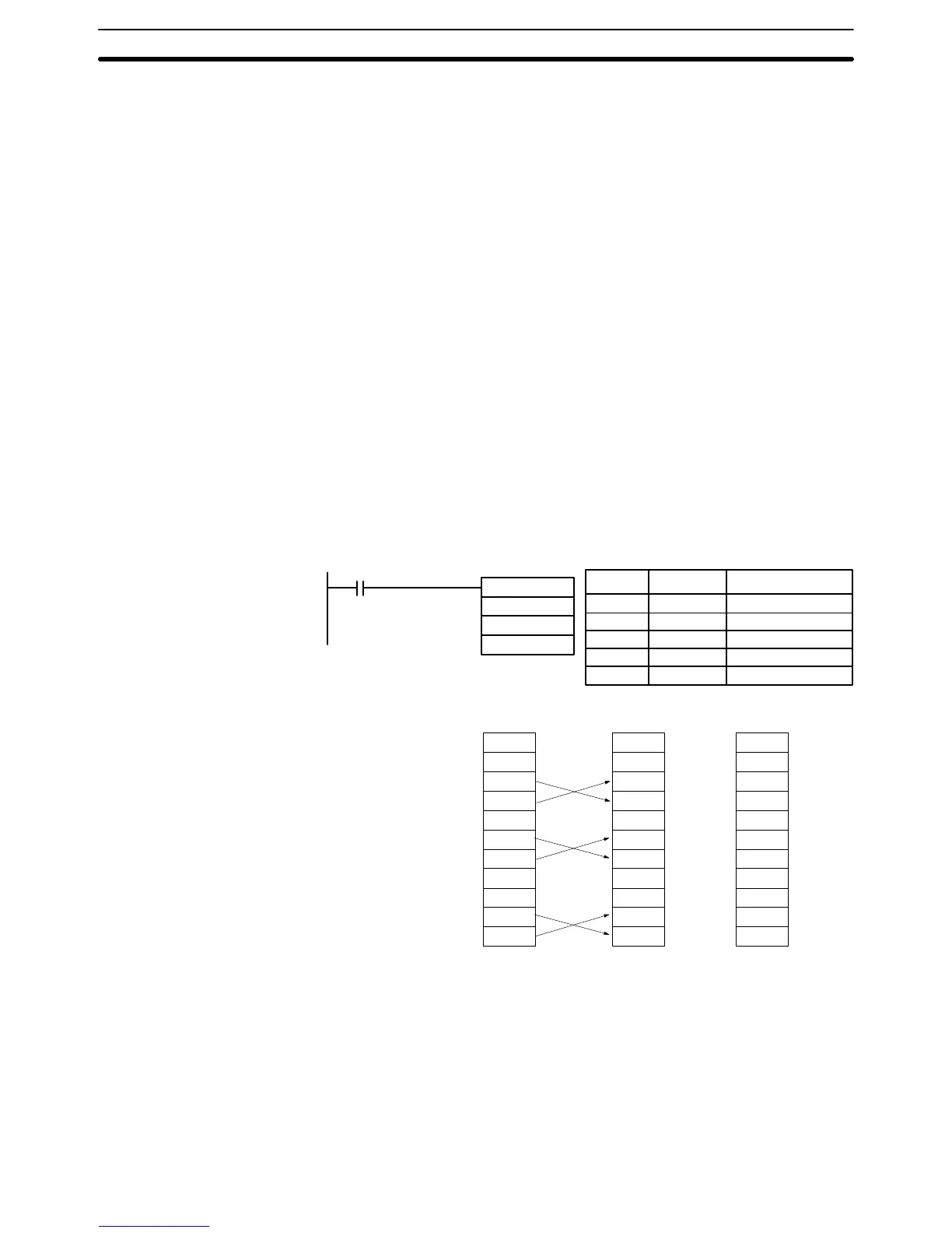
Example The following example shows instruction ASFT(17) used to shift words in an
11-word shift register created between DM 0100 and DM 0110 with a control
word
value of #6000 (bits 13 and 14 ON). The data changes that would occur for
the given register and control word contents are also shown.
ASFT(17)
#6000
DM 0100
DM 0110
00000
Address Instruction Operands
00100 LD 00000
00101 ASFT(17)
# 6000
DM 0100
DM 0110
1234
0000
0000
2345
3456
0000
4567
5678
6789
0000
789A
Before
execution
DM
0100
DM 0101
DM 0102
DM 0103
DM 0104
DM 0105
DM 0106
DM 0107
DM 0108
DM 0109
DM 0110
1234
0000
2345
0000
3456
4567
0000
5678
6789
789A
0000
1234
2345
3456
4567
5678
6789
789A
0000
0000
0000
0000
After 1
execution
After 7
executions
5-16 Data Movement
This
section describes the
instructions used for moving data between dif
ferent
addresses in data areas. These movements can be programmed to be within
the
same data area or between dif
ferent data
areas. Data movement is essential
for
utilizing all of the data areas of the PC. Ef
fective communications in Link Sys
-
tems also requires data movement. All of these instructions change only the
content of the words to which data is being moved, i.e., the content of source
words is the same before and after execution of any of the data movement in-
structions.
Data Movement Section 5-16