31
3-3 IR (Internal Relay) Area
The
IR area is used both as data to control I/O points, and as work bits to manipu
-
late and store data internally. It is accessible both by bit and by word. In the
C200HS PC, the IR area is comprised of words 000 to 235 and 298 to 511.
Words
in the IR area that are used to control I/O points are called I/O words. Bits
in
I/O words are called I/O bits. Bits in
the IR area which are not assigned as I/O
bits
can be used as work bits. IR area work bits are reset when power is
inter
-
rupted or PC operation is stopped.
I/O Words If
a Unit brings inputs into the PC, the bit assigned to it is an input bit; if the Unit
sends an output from the PC, the bit is an output bit. To turn on an output, the
output
bit assigned to it must be turned ON. When an input
turns on, the input bit
assigned
to it also turns ON. These
facts can be used in the program to access
input status and control output status through I/O bits.
Input Bit Usage Input
bits can be used to directly input external signals to the PC and can be used
in
any order in programming. Each input bit can also be
used in as many instruc
-
tions
as required to achieve ef
fective and proper control. They cannot be used in
instructions that control bit status, e.g., the OUTPUT, DIFFERENTIATION UP,
and KEEP instructions.
Output Bit Usage Output
bits are used to output program execution results and can be used in any
order in programming. Because outputs are refreshed only once during each
cycle
(i.e., once each time the program is executed), any output bit can be used
in only one instruction that controls its status, including OUT, KEEP(11),
DIFU(13),
DIFD(14) and SFT(10). If an output bit is used in more than one such
instruction,
only the status
determined by the last instruction will actually be out
-
put from the PC.
See
5-15-1 Shift
Register – SFT(10)
for an example that uses an output bit in two
‘bit-control’ instructions.
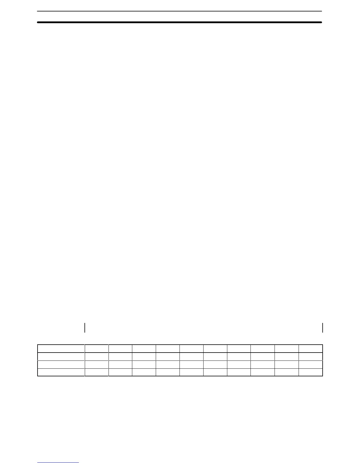
Word Allocation for Racks I/O
words
are allocated to the CPU Rack and Expansion I/O Racks by slot posi
-
tion.
One I/O word is allocated to each slot, as shown in the following table. Since
each
slot is allocated only one I/O word, a 3-slot rack uses only the first 3 words,
a
5-slot rack
uses only the first 5 words, and an 8-slot rack uses only the first 8
words.
W
ords that are allocated to
unused or nonexistent slots are available as
work words.
← Left side of rack Right side of a 10-slot rack →
Rack Slot 1 Slot 2 Slot 3 Slot 4 Slot 5 Slot 6 Slot 7 Slot 8 Slot 9 Slot 10
CPU IR 000 IR 001 IR 002 IR 003 IR 004 IR 005 IR 006 IR 007 IR 008 IR 009
1
st
Expansion IR 010 IR 011 IR 012 IR 013 IR 014 IR 015 IR 016 IR 017 IR 018 IR 019
2
nd
Expansion IR 020 IR 021 IR 022 IR 023 IR 024 IR 025 IR 026 IR 027 IR 028 IR 029
Unused Words Any
words allocated to a Unit that does not use them can be
used in program
-
ming as work words and bits. Units that do not used the words assigned to the
slot
they are mounted to include Link Units (e.g., Host Link Units, PC Link Units,
SYSMAC NET Link Units, etc.), Remote I/O Master Units, Special I/O Units,
Group-2 High-density I/O Units, Group-2 B7A Interface Units, and Auxiliary
Power Supply Units.
IR Area Section 3-3