48
Save IOM to Cassette Bit SR bit 27300 turns ON when IOM is saved to a Memory Cassette.
Load IOM from Cassette Bit SR bit 27301 turns ON when loading to IOM from a Memory Cassette.
3-4-26 Transfer Error Flags
Data
will not be
transferred from IOM to the Memory Cassette if an error occurs
(except for Read Only Error).
SR
bit 27312 turns ON when attempting to transfer data in
other than Program
Mode.
Transfer Error Flag SR bit 27313 turns ON when attempting to transfer data in Read-only Mode.
Transfer Error Flag SR
bit 27314 turns ON when attempting to transfer data and IOM capacity is in
-
sufficient.
3-4-27 PC Setup Error Flags
PC Setup Startup Error SR bit 27500 turns ON when a PC Setup Startup error occurs (DM6600 to
DM6614).
PC Setup RUN Error SR bit 27501 turns ON when a PC Setup Run error occurs (DM6615 to
DM6644).
SR
bit 27501
turns ON when a PC Setup Communications, Error setting or Mis
-
cellaneous error occurs (DM6645 to DM6655).
Minutes (00 to 59) SR bits 27600 to 27607 set the PC Clock to minutes (00 to 59).
Hours (00 to 23) SR bits 27608 to 27615 set the PC Clock to hours (0 to 23).
Keyboard Map Used for keyboard mapping.
3-5 AR (Auxiliary Relay) Area
AR
word addresses extend from AR 00 to
AR 27; AR bit addresses extend from
AR 0000 to AR 2715. Most AR area words and bits are dedicated to specific
uses,
such as transmission counters, flags,
and control bits, and words AR 00
through
AR 07 and AR 23 through AR 27 cannot be used for any other purpose.
Words
and bits from AR 08 to AR 22 are available as work words and
work bits if
not used for the following assigned purposes.
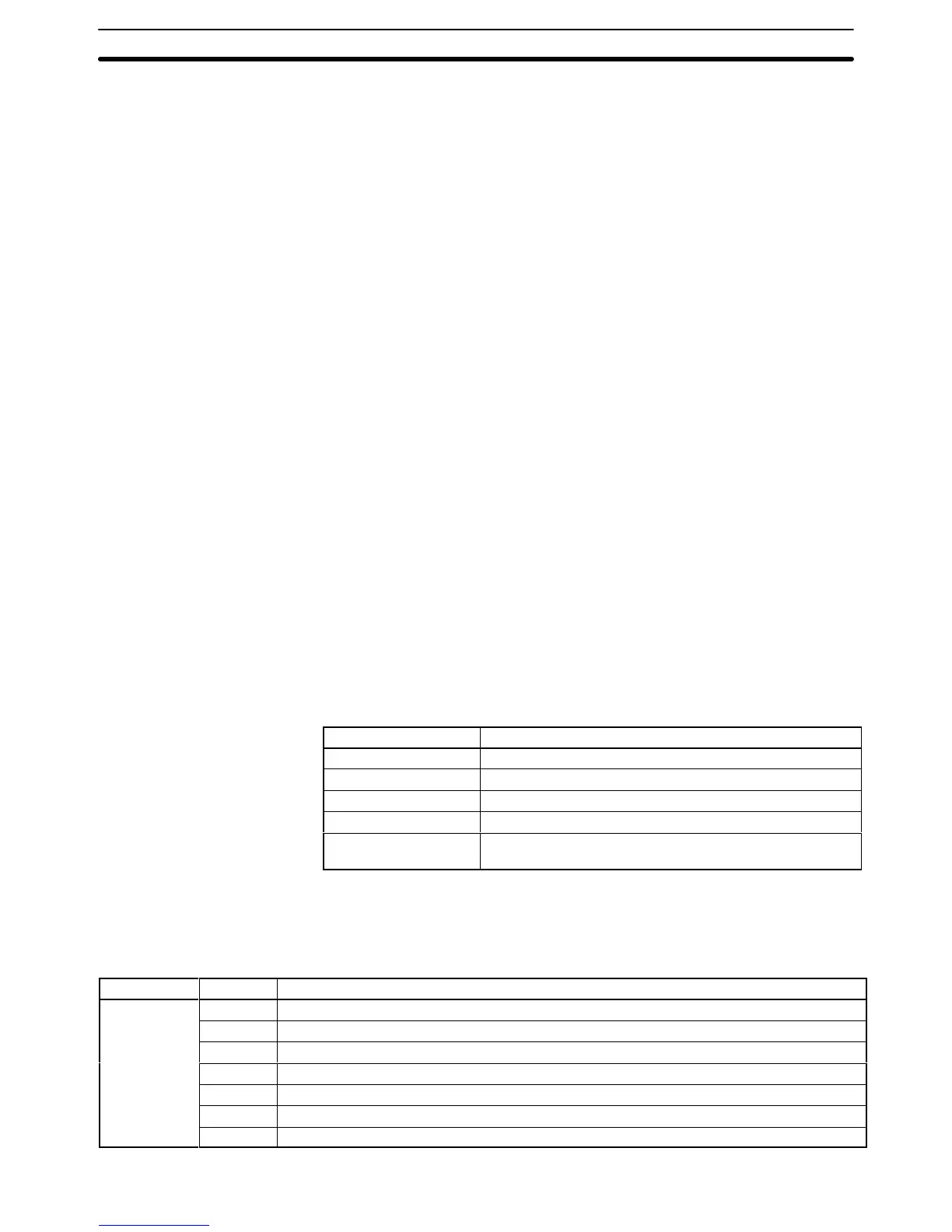
Word Use
AR 0713 to AR 0715 Error History Area
AR 07 to 15 SYSMAC LINK Units
AR 16, AR 17 SYSMAC LINK and SYSMAC NET Link Units
AR 18 to AR 21 Calendar/clock Area
AR 0708, AR 0709,
and AR 22
TERMINAL Mode Key Bits
The AR area retains status during power interruptions, when switching from
MONITOR or RUN mode to PROGRAM mode, or when PC operation is
stopped.
Bit allocations are shown in the
following table and described in the fol
-
lowing pages in order of bit number.
AR Area Flags and Control Bits
Word(s) Bit(s) Function
00 00
to 09
Error Flags for Special I/O Units 0 to 9 (also function as Error Flags for PC Link Units)
10 Error Flag for operating level 1 of SYSMAC LINK or SYSMAC NET Link System
11 Error Flag for operating level 0 of SYSMAC LINK or SYSMAC NET Link System
12 Host Computer to Rack-mounting Host Link Unit Level 1 Error Flag
13 Host Computer to Rack-mounting Host Link Unit Level 0 Error Flag
14 Remote I/O Master Unit 1 Error Flag
15 Remote I/O Master Unit 0 Error Flag
Transfer Error Flag: Not
PROGRAM mode
PC Setup
Communications/Error
Setting/Misc. Error
AR Area Section 3-5