61
3-9 LR (Link Relay) Area
The LR area is used as a common data area to transfer information between
PCs. This data transfer is achieved through a PC Link System.
Certain
words will be allocated as the write words of
each PC. These words are
written by the PC and automatically transferred to the same LR words in the
other
PCs in the System. The write words of
the other PCs are transferred in as
read words so that each PC can access the data written by the other PCs in the
PC
Link System. Only the write
words allocated to the particular PC will be avail
-
able
for writing; all other words may be read only
. Refer to the
PC Link System
Manual for details.
The LR area is accessible either by bit or by word. LR area word addresses
range
from LR 00 to LR 63; LR area bit addresses, from LR 0000 to LR 6315. Any
part
of the LR area that is not used by the PC Link System can be used as work
words or work bits.
LR area data is not retained when the power is interrupted, when the PC is
changed
to PROGRAM mode, or when it is reset in an interlocked program
sec
-
tion.
Refer to
5-10 INTERLOCK and INTERLOCK
CLEAR – IL(02) and ILC(03)
for details on interlocks.
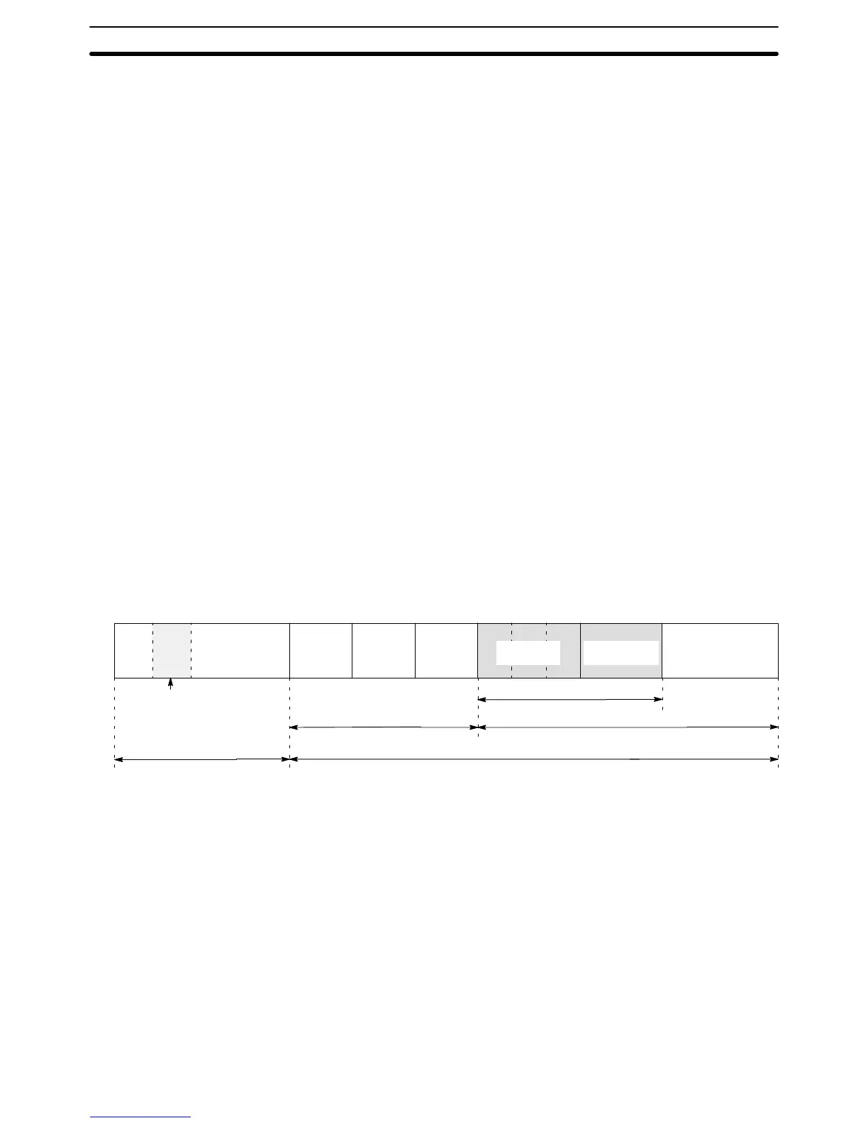
3-10 UM Area
With
the C200HS, the UM area is defined as the part of memory that can be con
-
verted
and transferred to ROM. The UM area is 16 KW of RAM which is backed
up by the CPU’s battery. Some of the UM area is reserved to system use, so
15,488
words can be used by the operator
. The structure of the C200HS DM and
UM areas is shown in the following illustration.
DM
0000
DM 6144 DM 6600 DM 6655 DM 7000 DM 9999
PC Setup
Reserved
Expansion
DM Area
I/O Comment
Area
Ladder program
V
ariable size
Ladder Program Area (15.1 KW)
Fixed DM Area
UM Area (16.0 KW)
Normal DM Area
Special I/O Unit Default Area
DM 1000 to DM 1999
Note Allocating
UM area for an expansion DM and/or
I/O Comment Area will reduce
program
capacity
. Check program capacity requirements before allocating the
UM area.
3-11 TR
(T
emporary Relay) Area
The
TR area provides eight bits that are used only with the LD and OUT instruc
-
tions
to enable
certain types of branching ladder diagram programming. The use
of TR bits is described in Section 4 Writing and Inputting the Program.
TR
addresses range from TR 0 though TR 7. Each of these bits can be used as
many
times as required and in any order required as long as the same LR bit is
not used twice in the same instruction block.
TR Area Section 3-11