EasyManua.ls Logo

Omron SYSMAC C200HS User Manual

Omron SYSMAC C200HS
503 pages
To Next Page IconTo Next Page
To Previous Page IconTo Previous Page
Page #192 background imageLoading...
Page #192 background image
182
Signed Binary Data BCD(24)
cannot be used to convert signed binary data directly to BCD. T
o con
-
vert
signed binary data, first determine whether the data
is positive or negative. If
it
is positive, BCD(24) can be used to convert the data to BCD. If it is negative,
use the 2’s COMPLEMENT – NEG(––) instruction to convert the data to un-
signed
binary before executing BCD(24). Refer to page
29 for details on signed
binary data.
Flags ER: S is greater than 270F.
Indirectly
addressed DM word
is non-existent. (Content of
DM word is
not BCD, or the DM area boundary has been exceeded.)
EQ: ON when the result is zero.
5-18-4 DOUBLE BINARY-TO-DOUBLE BCD – BCDL(59)
S: First source word (binary)
IR, SR, AR, DM, HR, TC, LR
R: First result word
IR, SR, AR, DM, HR, LR
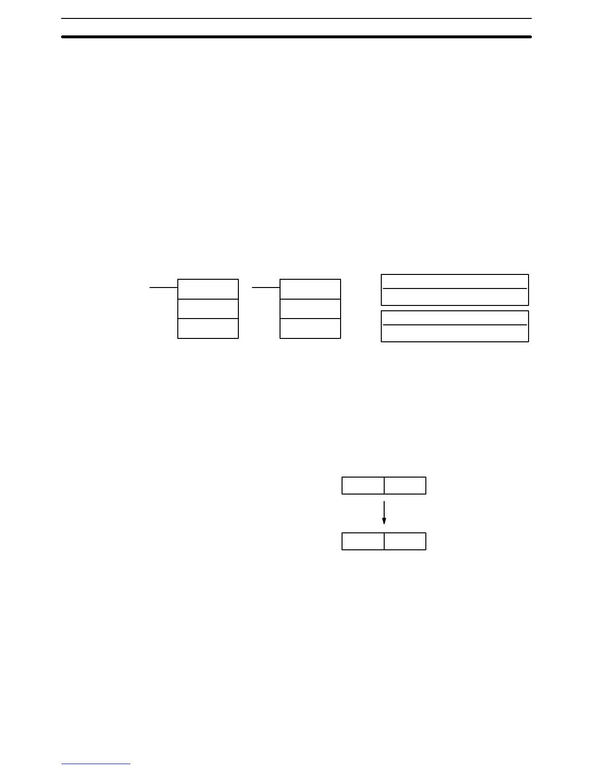
Ladder Symbols Operand Data Areas
BCDL(59)
S
R
@BCDL(59)
S
R
Limitations If the content of S exceeds 05F5E0FF, the converted result would exceed
99999999
and BCDL(59) will not be executed. When the instruction is not
exe
-
cuted, the content of R and R+1 remain unchanged.
S and S+1 must be in the same data area as must R and R+1.
Description BCDL(59) converts the 32-bit binary content of S and S+1 into eight digits of
BCD data, and outputs the converted data to R and R+1.
S
+ 1
S
R + 1
R
BCD
Binary
Signed Binary Data BCD(24)
cannot be used to convert signed binary data directly to BCD. T
o con
-
vert
signed binary data, first determine whether the data
is positive or negative. If
it
is positive, BCD(24) can be used to convert the data to BCD. If it is negative,
use
the DOUBLE 2’
s COMPLEMENT – NEGL(––) instruction to convert the data
to unsigned binary before executing BCD(24). Refer to page 29 for details on
signed binary data.
Flags ER: Content of R and R+1 exceeds 99999999.
Indirectly
addressed DM word
is non-existent. (Content of
DM word is
not BCD, or the DM area boundary has been exceeded.)
EQ: ON when the result is zero.
Data Conversion Section 5-18

Table of Contents

Other manuals for Omron SYSMAC C200HS

Questions and Answers:

Omron SYSMAC C200HS Specifications

General IconGeneral
ModelC200HS
ManufacturerOmron
SeriesSYSMAC
Humidity10 to 90% RH (non-condensing)
Programming LanguageLadder logic
Program MemoryRAM/EPROM/EEPROM
Communication ProtocolsSYSMAC LINK, SYSMAC NET
Communication PortsRS-232C, RS-422
Power Supply100-240V AC, 24V DC
Operating Temperature0 to 55°C
Vibration Resistance10 to 57 Hz, 0.075mm amplitude

Summary

SECTION 1 Introduction

1-1 Overview

Provides a general introduction to Programmable Controllers (PCs), their operation, and programming concepts.

SECTION 2 Hardware Considerations

2-1 CPU Components

Details the main components of the C200HS CPU, including indicators, fuses, and connection ports.

SECTION 3 Memory Areas

SECTION 4 Writing and Inputting the Program

4-4 Basic Ladder Diagrams

Introduces fundamental concepts of ladder diagram programming, including rungs, conditions, and instructions.

4-7 Inputting, Modifying, and Checking the Program

Details the procedures for entering, editing, checking, and debugging programs using the Programming Console.

SECTION 5 Instruction Set

5-8 Ladder Diagram Instructions

Details fundamental instructions used in ladder diagrams like LOAD, AND, OR, and their variations.

SECTION 6 Program Execution Timing

6-4 I/O Response Time

Details the time taken for the PC to respond to input signals and produce output signals.

SECTION 7 Program Monitoring and Execution

7-1 Monitoring Operation and Modifying Data

Covers procedures for observing and modifying PC data like bits, words, timers, and counters.

SECTION 8 Communications

8-2 Parameters for Host Link and RS-232C Communications

Details essential PC Setup parameters required for enabling Host Link and RS-232C communications.

SECTION 10 Troubleshooting

10-4 Error Messages

Lists common error messages, their probable causes, and possible corrections for diagnosing system problems.

SECTION 11 Host Link Commands

11-3 Host Link Commands

Details the various commands used for host computer communication with the C200HS PC.

Appendix B Programming Instructions

Appendix D Memory Areas

Appendix E PC Setup

RS-232C Port Settings (DM 6645 to DM 6649)

Details the specific parameters for configuring the RS-232C port, essential for communication setup.

Related product manuals