EasyManua.ls Logo

Omron SYSMAC C200HS User Manual

Omron SYSMAC C200HS
503 pages
To Next Page IconTo Next Page
To Previous Page IconTo Previous Page
Page #343 background imageLoading...
Page #343 background image
334
The
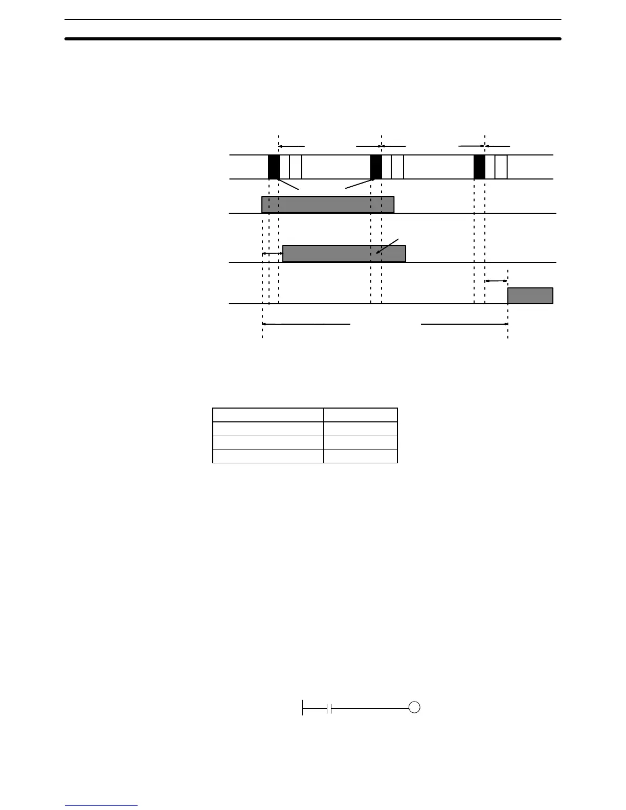
PC takes longest to respond when it receives the input signal just after the
I/O
refresh phase
of the cycle. In this case the CPU does not recognize the input
signal
until the end of the next cycle. The maximum response time is thus one
cycle longer than the minimum I/O response time, except that the I/O refresh
time
would not need to be added in because the input comes just after it rather
than before it.
Cycle
time
Input
signal
Output
signal
Cycle
Cycle time
I/O refresh
I/O response time
Input
ON
delay
Instruction
execution
Instruction
execution
Instruction
execution
CPU reads
input signal
Output
ON delay
Cycle time
Maximum I/O response time =
Input ON delay + (Cycle time x 2) + Output ON delay
Calculation Example The
data in the following table would produce the minimum and maximum cycle
times shown calculated below.
Item Time
Input ON-delay 1.5 ms
Output ON-delay 15 ms
Cycle time 20 ms
Minimum I/O response time = 1.5 + 20 + 15 = 36.5 ms
Maximum I/O response time = 1.5 + (20 x 2) +15 = 56.5 ms
Note In this example the I/O refresh time is negligible has not been included in the
minimum I/O response time.
6-4-2 Remote I/O Systems
With C200HS Remote I/O Systems, only the cycle
time of the PC needs to be
considered
in computing the I/O response times as long
as the remote I/O trans
-
mission
time is negligible and smaller than the cycle time. The cycle time, how
-
ever, is increased by the presence of the Remote I/O System.
The
processing that determines and the methods for calculating maximum and
minimum
response times from input to output are
provided in this section. Calcu
-
lations assume that both the input and the output are located on Slave Racks in a
Remote
I/O System, but the calculations are the same for I/O points on Optical
I/O Units, I/O Link Units, I/O Terminals, etc.
X
Input
on
Slave Rack
Output on
Slave Rack
Although
more precise
equations are possible if required, equations used for the
following calculations do not consider fractions of a scan.
Maximum I/O Response
Time
I/O Response Time Section 6-4

Table of Contents

Other manuals for Omron SYSMAC C200HS

Questions and Answers:

Omron SYSMAC C200HS Specifications

General IconGeneral
ModelC200HS
ManufacturerOmron
SeriesSYSMAC
Humidity10 to 90% RH (non-condensing)
Programming LanguageLadder logic
Program MemoryRAM/EPROM/EEPROM
Communication ProtocolsSYSMAC LINK, SYSMAC NET
Communication PortsRS-232C, RS-422
Power Supply100-240V AC, 24V DC
Operating Temperature0 to 55°C
Vibration Resistance10 to 57 Hz, 0.075mm amplitude

Summary

SECTION 1 Introduction

1-1 Overview

Provides a general introduction to Programmable Controllers (PCs), their operation, and programming concepts.

SECTION 2 Hardware Considerations

2-1 CPU Components

Details the main components of the C200HS CPU, including indicators, fuses, and connection ports.

SECTION 3 Memory Areas

SECTION 4 Writing and Inputting the Program

4-4 Basic Ladder Diagrams

Introduces fundamental concepts of ladder diagram programming, including rungs, conditions, and instructions.

4-7 Inputting, Modifying, and Checking the Program

Details the procedures for entering, editing, checking, and debugging programs using the Programming Console.

SECTION 5 Instruction Set

5-8 Ladder Diagram Instructions

Details fundamental instructions used in ladder diagrams like LOAD, AND, OR, and their variations.

SECTION 6 Program Execution Timing

6-4 I/O Response Time

Details the time taken for the PC to respond to input signals and produce output signals.

SECTION 7 Program Monitoring and Execution

7-1 Monitoring Operation and Modifying Data

Covers procedures for observing and modifying PC data like bits, words, timers, and counters.

SECTION 8 Communications

8-2 Parameters for Host Link and RS-232C Communications

Details essential PC Setup parameters required for enabling Host Link and RS-232C communications.

SECTION 10 Troubleshooting

10-4 Error Messages

Lists common error messages, their probable causes, and possible corrections for diagnosing system problems.

SECTION 11 Host Link Commands

11-3 Host Link Commands

Details the various commands used for host computer communication with the C200HS PC.

Appendix B Programming Instructions

Appendix D Memory Areas

Appendix E PC Setup

RS-232C Port Settings (DM 6645 to DM 6649)

Details the specific parameters for configuring the RS-232C port, essential for communication setup.

Related product manuals