42
The
status of SR 2521
1 and thus the status of force-set and force-reset bits can
be
maintained when power is turned of
f and on by enabling
the Forced Status
Hold
Bit in the PC Setup. If the Forced Status Hold Bit is enabled, the status of
SR
2521
1 will be preserved when power is turned of
f and on. If this is done and
SR
2521
1 is ON, then the status of force-set and force-reset bits will also be pre
-
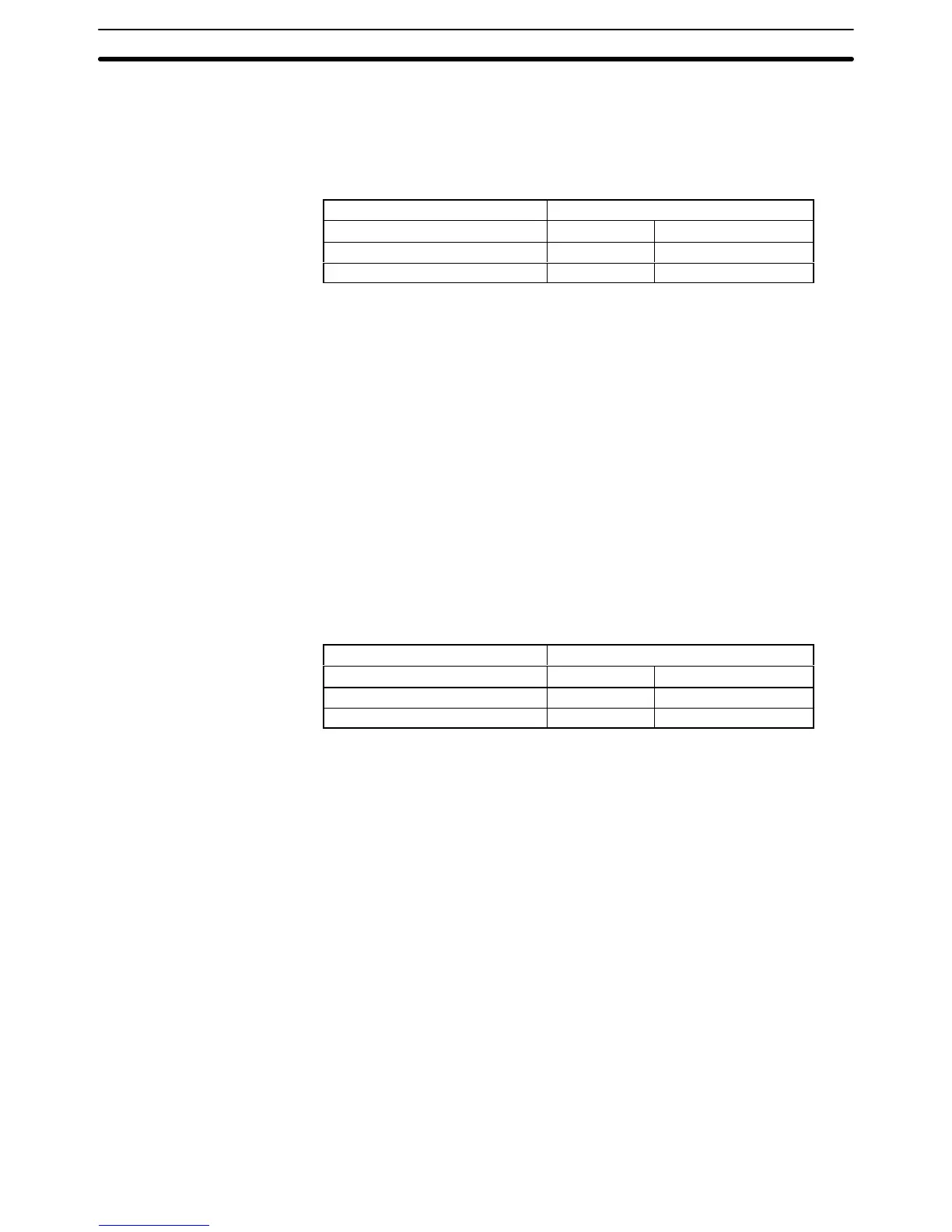
served, as shown in the following table.
Status before shutdown Status at next startup
SR 25211 SR 25211 Force-set/reset bits
ON ON Status maintained
OFF OFF Reset
Note Refer to 3-6-4 PC Setup for details on enabling the Forced Status Hold Bit.
3-4-5 I/O Status Hold Bit
SR
25212 determines whether or not the status of IR and LR area bits is main
-
tained
when operation is started or stopped,
when operation begins by switching
from
PROGRAM mode to MONIT
OR or RUN modes. If SR 25212 is ON, bit
sta
-
tus
will be
maintained; if SR 25212 is OFF
, all IR and LR area bits will be reset.
The I/O Status Hold Bit is effective only if enabled in the PC Setup.
The status of SR 25212 in not affected by a power interruption unless the I/O
table is registered; in that case, SR 25212 will go OFF.
SR 25212 should be manipulated from a Peripheral Device, e.g., a Program-
ming Console or LSS.
The
status of SR 25212 and thus the status of IR and LR area bits can be main
-
tained
when power is turned of
f and on by enabling the I/O Status Hold Bit in the
PC Setup. If the I/O Status Hold Bit is enabled, the status of SR 25212 will be
preserved
when power is
turned of
f and on. If this is done and SR 25212 is ON,
then the status of IR and LR area bits will also be preserved, as shown in the
following table.
Status before shutdown Status at next startup
SR 25212 SR 25212 IR and LR bits
ON ON Status maintained
OFF OFF Reset
Note Refer to 3-6-4 PC Setup for details on enabling the I/O Status Hold Bit.
3-4-6 Output OFF Bit
SR
bit 25215 is turned ON
to turn OFF all outputs from the PC. The OUT INHIBIT
indicator on the front panel of the CPU will light. When the Output OFF Bit is OFF
,
all output bits will be refreshed in the usual way.
The
status of the Output OFF Bit is maintained for power interruptions or when
PC operation is stopped, unless the I/O table has been registered, or the I/O
table
has been registered and either the Forced Status Hold Bit or the I/O Status
Hold Bit has not been enabled in the PC Setup.
3-4-7 FAL (Failure Alarm) Area
A
2-digit BCD F
AL code is output to bits 25300 to 25307 when the F
AL or F
ALS
instruction
is executed. These codes are user defined for use in error diagnosis,
although the PC also outputs F
AL codes to these bits, such as one caused by
battery voltage drop.
This
area can be reset by executing the F
AL
instruction with an operand of 00 or
by performing a Failure Read Operation from the Programming Console.
3-4-8 Low Battery Flag
SR bit 25308 turns ON if the voltage of the CPU’s backup battery drops. The
ALM/ERR indicator on the front of the CPU will also flash.
Maintaining Status during
Startup
Maintaining Status during
Startup
SR Area Section 3-4