191
When
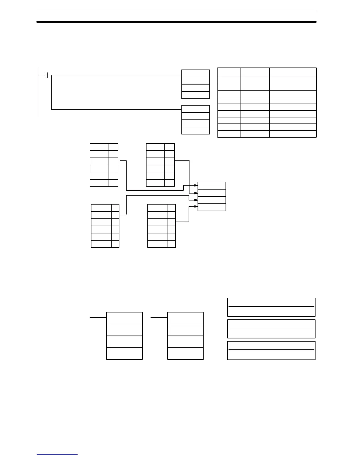
00000 is ON, the following diagram encodes IR words 010 and 01
1 to the
first
two digits of HR 20 and then encodes LR 10 and 1
1 to
the last two digits of
HR 20. Although the status of each source word bit is not shown, it is assumed
that the bit with status 1 (ON) shown is the highest bit that is ON in the word.
00000
DMPX(77)
010
HR 20
#0010
LR 10
HR 20
#0012
IR 010
01000
:
01011 1
01012 0
: :
:
01015 0
LR 10
LR 1000
LR 1001
1
LR 1002
0
: :
:
: :
:
LR 1015
0
Digit
0
IR 01
1
01100
:
01109 1
01110 0
: :
:
01115 0
Digit
1
Digit 2
Digit 3
B
9
1
8
LR 1
1
LR 1
100
:
LR 1
108 1
LR 1
109 0
: :
:
LR 1
115 0
HR 20
DMPX(77)
Address Instruction Operands
00000 LD 00000
00001 DMPX(77)
010
HR 20
# 0010
00002 DMPX(77)
LR 10
HR 20
# 0012
5-18-9 7-SEGMENT DECODER – SDEC(78)
S: Source word (binary)
IR, SR, AR, DM, HR, TC, LR
Di: Digit designator
IR, SR, AR, DM, HR, TC, LR, #
Ladder Symbols
Operand Data Areas
D: First destination word
IR, SR, AR, DM, HR, LR
SDEC(78)
S
Di
D
@SDEC(78)
S
Di
D
Limitations Di must be within the values given below
All destination words must be in the same data area.
Description When
the execution condition is OFF
, SDEC(78) is not executed. When the exe
-
cution
condition is ON, SDEC(78) converts
the designated digit(s) of S into the
equivalent 8-bit, 7-segment display code and places it into the destination
word(s) beginning with D.
Example:
16-bit to 4-bit Encoding
Data Conversion Section 5-18