EasyManua.ls Logo

Omron SYSMAC C200HS User Manual

Omron SYSMAC C200HS
503 pages
To Next Page IconTo Next Page
To Previous Page IconTo Previous Page
Page #244 background imageLoading...
Page #244 background image
!
234
If
bit 15 of C is ON and more than one address contains the same maximum val
-
ue, the position of the lowest of the addresses will be output to D+1.
The
number of words within the range (N) is contained in the 3 rightmost digits of
C, which must be BCD between 001 and 999.
When
bit 15 of C is OFF
, data
within the range is treated as normal binary and
when it is ON the data is treated as signed binary.
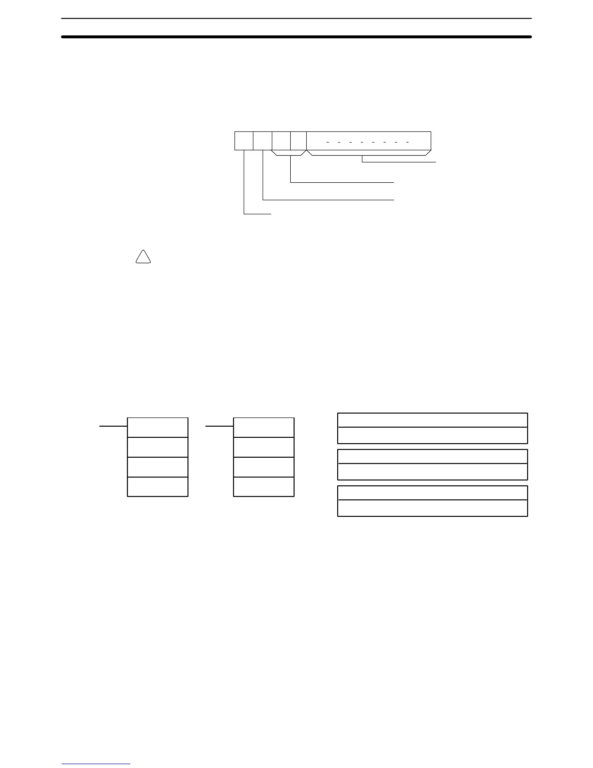
15 14 13 12 11 00
Data
type
1 (ON):
Signed binary
0 (OFF):
Normal binary
Number of words
in range (N)
Not used – set to zero.
Output address to D+1?
1 (ON): Yes.
0 (OFF): No.
C:
Caution If
bit 14 of C is ON, values above #8000 are treated
as negative numbers, so the
results
will dif
fer depending on the specified data type. Be sure that the correct
data type is specified.
Flags ER: Indirectly
addressed
DM word is non-existent. (Content of
:
DM word is
not BCD, or the DM area boundary has been exceeded.)
The number of words specified in C is not BCD (000 to 999).
R
1
and R
1
+N–1 are not in the same data area.
EQ: ON when the maximum value is #0000.
5-21-2 FIND MINIMUM – MIN(––)
R
1
: First word in range
IR, SR, AR, DM, HR, TC, LR
C: Control data
IR, SR, AR, DM, HR, TC, LR
Ladder Symbols Operand Data Areas
@MIN(––)
C
R
1
D
D: Destination word
IR, SR, AR, DM, HR, LR
MIN(––)
C
R
1
D
Limitations N in C must be BCD between 001 to 999.
R
1
and R
1
+N–1 must be in the same data area.
Description When
the execution condition is OFF
,
MIN(––) is not executed. When the execu
-
tion
condition is ON, MIN(––) searches the range of
memory from R
1
to R
1
+N–1
for
the address that contains the minimum value and outputs the minimum value
to the destination word (D).
If bit 14 of C is ON, MIN(––) identifies the address of the word containing the
minimum value in D+1. The address is identified differently for the DM area:
1, 2, 3... 1. For
an address
in the DM area, the word address is written to D+1. For ex
-
ample,
if the address containing the minimum value is DM 01
14, then #01
14
is written in D+1.
2. For
an address in another data area, the number of addresses from the be
-
ginning of the search is written to D+1. For example, if
the address contain
-
ing the minimum value is IR 114 and the first word in the search range is
IR 014, then #0100 is written in D+1.
Special Math Instructions Section 5-21

Table of Contents

Other manuals for Omron SYSMAC C200HS

Questions and Answers:

Omron SYSMAC C200HS Specifications

General IconGeneral
ModelC200HS
ManufacturerOmron
SeriesSYSMAC
Humidity10 to 90% RH (non-condensing)
Programming LanguageLadder logic
Program MemoryRAM/EPROM/EEPROM
Communication ProtocolsSYSMAC LINK, SYSMAC NET
Communication PortsRS-232C, RS-422
Power Supply100-240V AC, 24V DC
Operating Temperature0 to 55°C
Vibration Resistance10 to 57 Hz, 0.075mm amplitude

Summary

SECTION 1 Introduction

1-1 Overview

Provides a general introduction to Programmable Controllers (PCs), their operation, and programming concepts.

SECTION 2 Hardware Considerations

2-1 CPU Components

Details the main components of the C200HS CPU, including indicators, fuses, and connection ports.

SECTION 3 Memory Areas

SECTION 4 Writing and Inputting the Program

4-4 Basic Ladder Diagrams

Introduces fundamental concepts of ladder diagram programming, including rungs, conditions, and instructions.

4-7 Inputting, Modifying, and Checking the Program

Details the procedures for entering, editing, checking, and debugging programs using the Programming Console.

SECTION 5 Instruction Set

5-8 Ladder Diagram Instructions

Details fundamental instructions used in ladder diagrams like LOAD, AND, OR, and their variations.

SECTION 6 Program Execution Timing

6-4 I/O Response Time

Details the time taken for the PC to respond to input signals and produce output signals.

SECTION 7 Program Monitoring and Execution

7-1 Monitoring Operation and Modifying Data

Covers procedures for observing and modifying PC data like bits, words, timers, and counters.

SECTION 8 Communications

8-2 Parameters for Host Link and RS-232C Communications

Details essential PC Setup parameters required for enabling Host Link and RS-232C communications.

SECTION 10 Troubleshooting

10-4 Error Messages

Lists common error messages, their probable causes, and possible corrections for diagnosing system problems.

SECTION 11 Host Link Commands

11-3 Host Link Commands

Details the various commands used for host computer communication with the C200HS PC.

Appendix B Programming Instructions

Appendix D Memory Areas

Appendix E PC Setup

RS-232C Port Settings (DM 6645 to DM 6649)

Details the specific parameters for configuring the RS-232C port, essential for communication setup.

Related product manuals