302
If
there are 8 digits of source
data, they are placed in S and S+1, with the most
significant digits placed in S+1. If there are 4 digits of source data, they are
placed in S.
7SEG(––) displays the 4 or 8-digit data in 12 cycles, and then starts over and
continues displaying the data.
The
7-segment display must provide four data lines and one latch signal line for
each display digit.
Note 1. Consider the cycle time and the characteristics of the 7-segment display
when designing the system.
2. Output bits not used here can be used as ordinary output bits.
Precautions I/O
refreshing must be performed for all I/O points used by 7SEG(––) each time it
is executed to ensure effective operation. The I/O REFRESH instruction must
thus
be used with 7SEG(––) whenever 7SEG(––) is used in a subroutine to en
-
sure
that the I/O points are refreshed each
execution. Refer to page
315 for an
example of this type of programming.
7SEG(––)
will be executed from
the first cycle whenever program execution is
started, including restarts made after power interruptions.
Do not use 7SEG(––) more than once in the program.
7SEG(––) cannot be used for I/O Units mounted to Slave Racks.
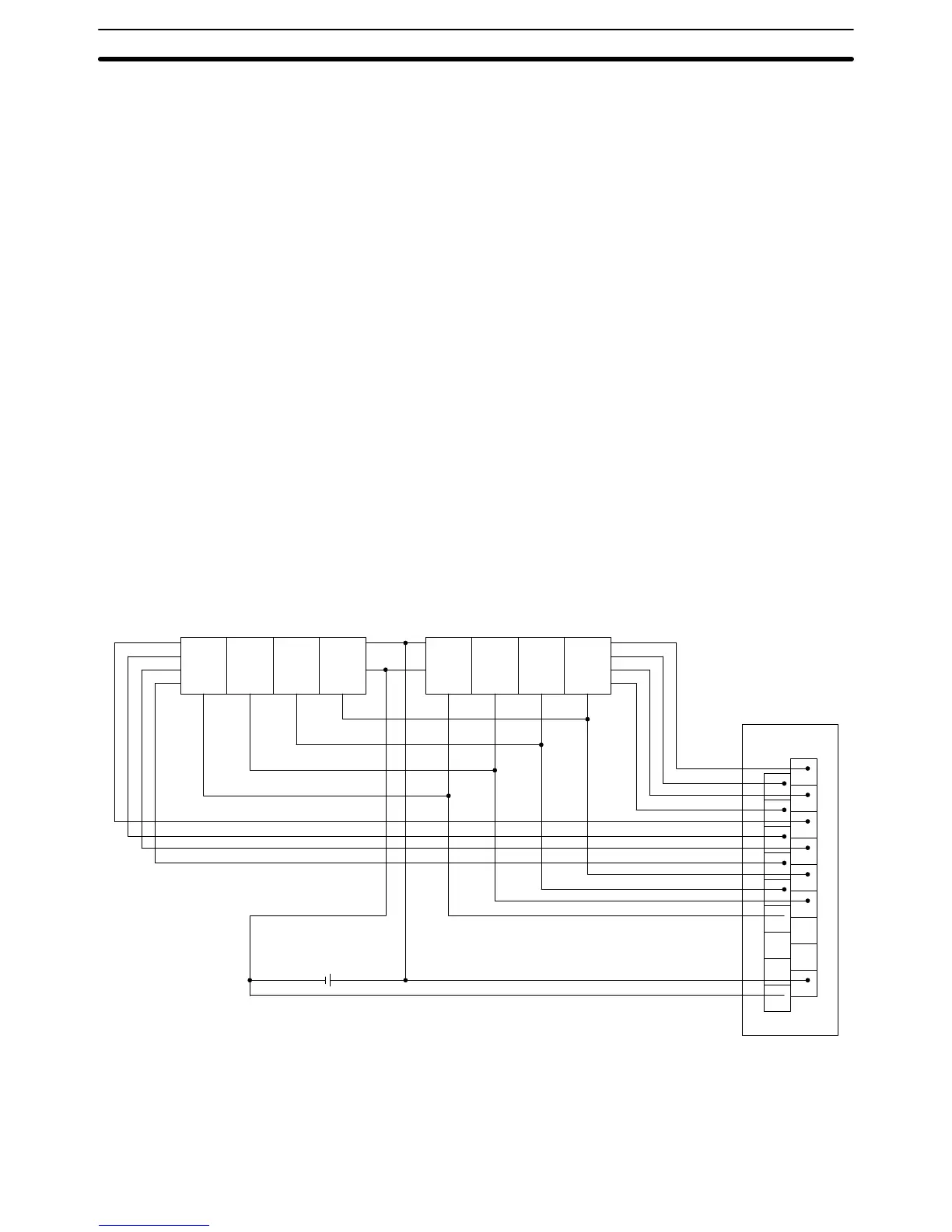
Hardware This
instruction outputs word data to a 7-segment display
. It utilizes either 8 out
-
put
bits for 4 digits or 12 output bits for 8 digits. The 7-segment
display is con
-
nected
to an Output Unit as shown in the diagram below
. For 4-digit display
, the
data outputs (D0 to D3) are connected to output points 0 through 3 (allocated
word O), and latch outputs (CS0 to CS3) are connected to output points 4
through 7. Output point 12 (for 8-digit display) or output point 8 (for 4-digit dis-
play)
will be turned ON when one round of data is displayed, but there is no need
to connect them unless required by the application.
1
3
5
7
9
11
13
15
COM
0
2
4
6
8
10
12
14
DC
OD212
D
0
D
1
D
2
D
3
V
DD
(+)
V
SS
(0)
LE3 LE2 LE1 LE0
D
0
D
1
D
2
D
3
V
DD
(+)
V
SS
(0)
LE3 LE2 LE1 LE0
The
outputs must be
connected from an Output Unit with 8 or more output points
for
four digits or
16 or more output points for eight digits. Basic Output, Special
I/O, or High-density Output Units can be used.
Note 1. Output
Unit outputs normally employ negative logic. (Only the PNP output
type employs positive logic.)
Advanced I/O Instructions Section 5-28