301
5-28 Advanced I/O Instructions
Advanced
I/O instructions enable control, with
a single instruction, of previously
complex
operations involving external I/O devices (digital switches, 7-segment
displays, etc.).
There
are five advanced I/O instructions, as shown in the following table. All of
these
are expansion instructions and must be assigned to function codes before
they can be used.
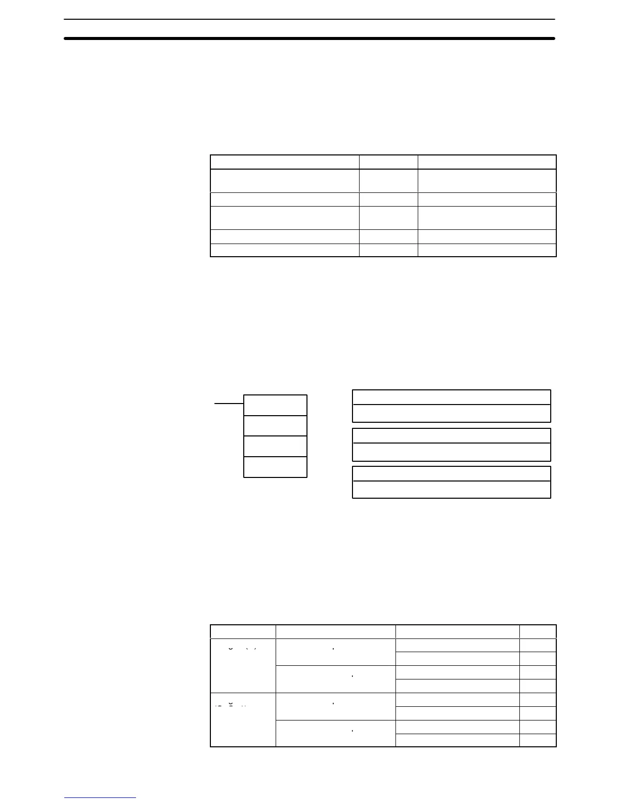
Name Mnemonic Function
7-SEGMENT DISPLAY OUTPUT 7SEG(––) BCD output to 7-segment dis-
play
DIGITAL SWITCH INPUT DSW(––) Data input from a digital switch
HEXADECIMAL KEY INPUT HKY(––) Hexadecimal input from 16-key
keypad
TEN-KEY INPUT TKY(––) BCD input from 10-key keypad
MATRIX INPUT MTR(––) Data input from an 8 x 8 matrix
Although
TKY(––) is used only to simplify programming, the other advanced I/O
instructions
can be used to shorten cycle time, reduce the need for Special
I/O
Units,
and reduce system
cost. With the exception of TKY(––), however
, the ad
-
vanced
I/O instructions can only be used once each in the
program and cannot
be
used for I/O Units mounted to Slave Racks, where Special I/O Units must be
used.
5-28-1 7-SEGMENT DISPLAY OUTPUT – 7SEG(––)
S: First source word
IR, SR, AR, DM, HR, TC, LR
Ladder Symbols Operand Data Areas
7SEG(––)
S
O
C
C: Control data
000 to 007
O: Output word
IR, SR, AR, HR, LR
Limitations S and S+1 must be in the same data area.
Do not set C to values other than 000 to 007.
Overview When
the execution condition is OFF
, 7SEG(––) is not executed. When the exe
-
cution
condition is ON, 7SEG(––) reads the source data (either 4 or 8-digit), con
-
verts
it to 7-segment display data, and outputs that data to the 7-segment display
connected to the output indicated by O.
The
value of C indicates the
number of digits of source data and the logic for the
Input and Output Units, as shown in the following table.
Source data Display’s data input logic Display’s latch input logic C
4 digits (S) Same as Output Unit
Same as Output Unit 0000